Electric Circuit Drawing
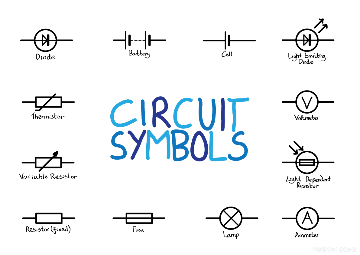
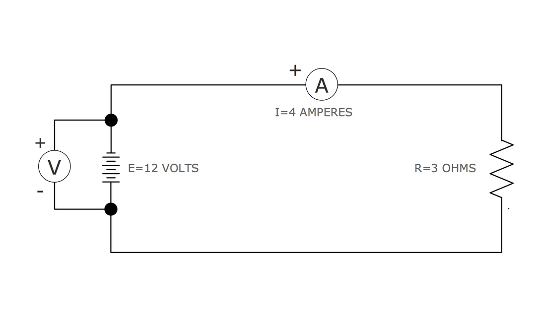
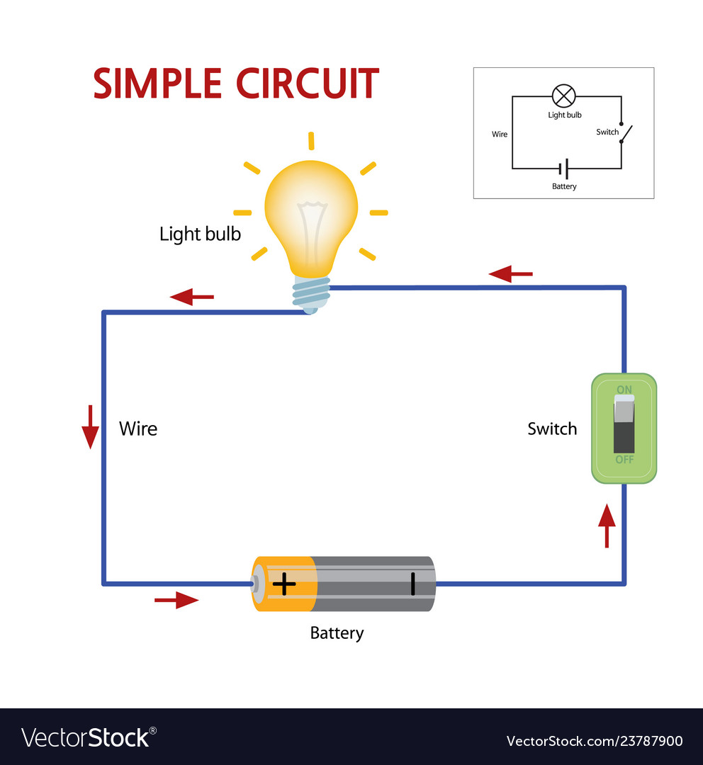
Electric Circuit Drawing - Electrical symbols are the most commonly used symbols in circuit diagramming. A circuit diagram could either be pictorial or schematic. The schematic diagram of the vco core where c is the equivalent parallel capacitance, cunit is the unit capacitance of the capacitor array, cvar is the capacitance of the varactors and n is the number of the switches with turning on. 753k views 5 years ago electric currents and effects class 07. Start with a collection of electrical symbols appropriate for your diagram. Web circuit symbols and circuit diagrams. Web in electrical and electronics engineering, we use different types of drawings or diagrams to represent a certain electrical system or circuit. Amplifiers (denoted by triangle shapes) increase the output signal in your circuit. Web circuito.io is an automatic generator of circuit schematics and code. Draw circuits represented by lines. Web electrical circuit diagram symbols. Web a circuit diagram allows you to visualize how components of a circuit are laid out. Seamless circuit design for your project. These two different types of circuit diagrams are called pictorial (using basic images) or schematic style (using industry standard. Web circuit symbols and circuit diagrams. Explore and start with a circuit diagram template in the uml section of our template library or create a new document in lucidchart. Web electrical circuit diagram symbols. Web in electrical and electronics engineering, we use different types of drawings or diagrams to represent a certain electrical system or circuit. Smartdraw comes with thousands of detailed electrical symbols you can. Lines connect fuses, switches, capacitors, inductors, and more. You plan your circuit by picking the high level electronic blocks, and circuito.io does all the rest. Thus far, this unit of the physics classroom tutorial has focused on the key ingredients of an electric circuit and upon the concepts of electric potential difference, current and resistance. It serves as a visual. This tutorial should turn you into a fully literate schematic reader! These electrical circuits are represented by lines to represent wires and symbols or icons to. Because there is only one group of varactors in this circuit, so that n Click create > new document. Web circuito.io is an automatic generator of circuit schematics and code. Symbol usage depends on the audience viewing the diagram. The input shu working voltage can be divided into dc 1.5v, 3v, 6v, 9v, etc. Understanding how to read and follow schematics is an important skill for any electronics engineer. We'll go over all of the fundamental schematic symbols: A circuit diagram could either be pictorial or schematic. Web electrical circuit diagram symbols. 753k views 5 years ago electric currents and effects class 07. Schematics are our map to designing, building, and troubleshooting circuits. The ability to read electrical schematics is a really useful. The network of transistors, transformers, capacitors, connecting wires, and other electronic components within a single device such as a radio is also an electric circuit. Draw circuits represented by lines.
Electrical Circuit Diagrams Symbols

Electrical Symbols Electrical Circuits

Electric Circuit Diagram With Labels
We've Seen The Symbols Of The Most Common Electrical Components That Are Used To Represent Them.
Web In Electrical And Electronics Engineering, We Use Different Types Of Drawings Or Diagrams To Represent A Certain Electrical System Or Circuit.
They’re Like A Map For Building Or Troubleshooting Circuits, And Can Tell You Almost Everything You Need To Know To Understand How A Circuit Works.
Drag And Drop Symbols To The Circuits And Connect Them.
Related Post: