Piping And Instrumentation Drawing
Piping And Instrumentation Drawing - A link to download this p&id is given at the end of the page. Available for windows, mac and linux. In other words it is also called a process and instrumentation diagram or simply a p&i diagram or drawing. Modern alternative to pencil and paper. To read and understand engineering fluid diagrams and prints, usually referred to as p&ids, an individual must be familiar with the basic symbols. Web p&id is short for “piping and instrumentation diagram”. Valves are used to control the direction, flow rate, and pressure of fluids. Through a p&id, you can get the following information: It is also called as mechanical flow diagram (mfd). It serves as a vital tool in the process industry, forming the backbone of the design phase and providing a detailed layout of the plant's process. Get tired of hand sketches and look for something better to use? In other words it is also called a process and instrumentation diagram or simply a p&i diagram or drawing. It is also called as mechanical flow diagram (mfd). Web piping and instrumentation diagrams (p&ids) use specific symbols to show the connectivity of equipment, sensors, and valves in a. After exploring lots of videos and articles about p&ids we concluded that reading the valve symbols, lines, codes, etc. P&ids are foundational to the maintenance and modification of the process that it graphically represents. To be effective in the workplace, you must be able to read and interpret them. It's a simple way of using lines and symbols to tell. Web p&id drawing, or piping and instrumentation diagrams, is like a special map that shows how pipes and instruments work together in factories and plants. Function and purpose of p&ids. They offer a detailed overview of the process flow , including equipment, valves, and instrumentation, crucial for design and operational. Web p&id is short for “piping and instrumentation diagram”. This. Web a piping and instrumentation diagram (p&id) is a detailed drawing that shows the piping and instrumentation of a processing plant. Web a piping and instrumentation diagram displays the piping components (for example equipment, valves, reducers and so on) of an actual physical process flow and is often used in the engineering projects, such as setting up steam boilers, heat exchangers, electric boilers and more. This drawing is developed during the design stage of the plant and is later used to assist. Define the scope of the system before drawing a p&id. A link to download this p&id is given at the end of the page. Web a piping and instrumentation diagram (p&id) is a comprehensive schematic that illustrates the functional relationship of piping, instrumentation, and system equipment components within a process plant. Define the relationship between components. It includes all piping, instruments, valves, and equipment the system consists of. In other words it is also called a process and instrumentation diagram or simply a p&i diagram or drawing. Get tired of hand sketches and look for something better to use? Web p&id is short for “piping and instrumentation diagram”. These symbols can represent actuators, sensors, and controllers and may be apparent in most, if not all, system diagrams. It serves as a vital tool in the process industry, forming the backbone of the design phase and providing a detailed layout of the plant's process. Web a piping and instrumentation diagram, also called p&id, is a diagram used to show a graphical display of a complete system. They offer a detailed overview of the process flow , including equipment, valves, and instrumentation, crucial for design and operational. Function and purpose of p&ids.![How to read a piping and instrumentation drawing? [Video] Valve Solutions](https://1.bp.blogspot.com/-GgHH1pcU0W0/WlNHvPbeyZI/AAAAAAAAAQY/NO9bREo9MDQAdPValYZ3zicXM5egYb4ygCLcBGAs/w1200-h630-p-k-no-nu/bp129.jpg)
How to read a piping and instrumentation drawing? [Video] Valve Solutions
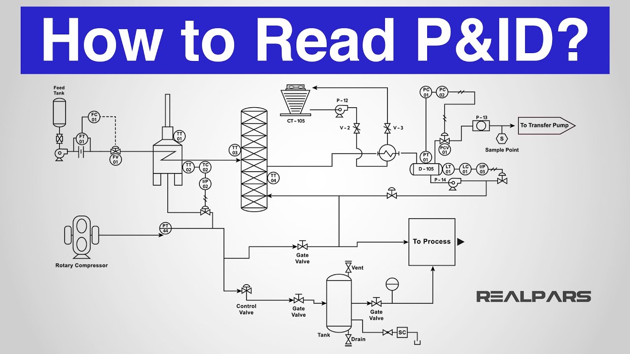
How to Read a P&ID? (Piping & Instrumentation Diagram) YouTube
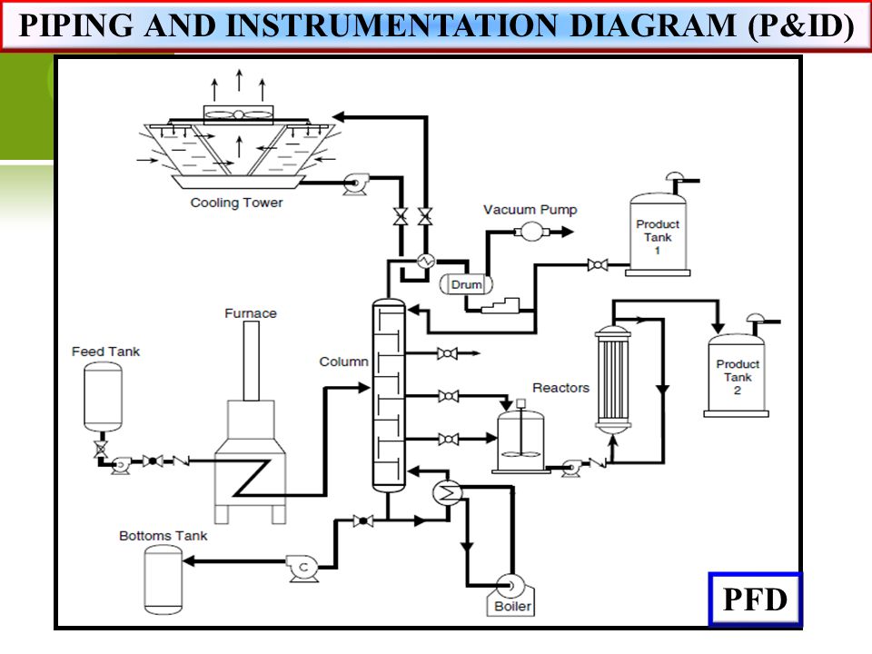
Piping and Instrumentation Diagram P&ID By TheEngineeringConcepts
Valves Are Used To Control The Direction, Flow Rate, And Pressure Of Fluids.
Web The Piping And Instrumentation Diagram Is Also Known As The Process Engineering Flow Scheme, Pefs.
To Be Effective In The Workplace, You Must Be Able To Read And Interpret Them.
To Facilitate Your Knowledge Of Piping & Instrumentation Drawings, Professor Barry M.
Related Post: