What Is A Schematic Drawing
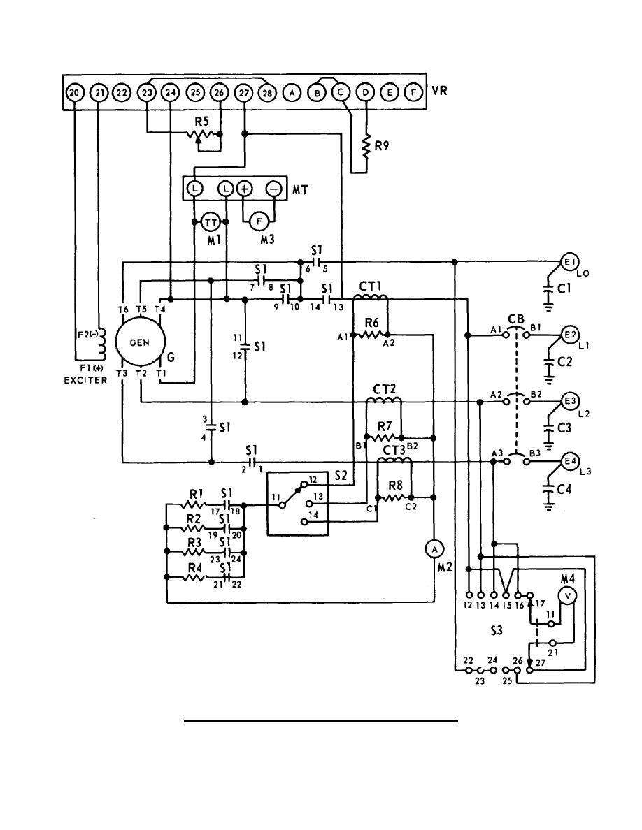
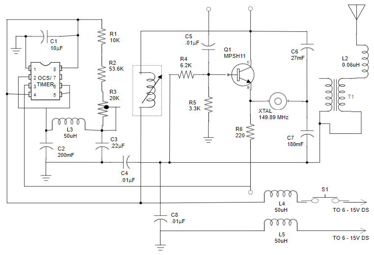
What Is A Schematic Drawing - Web a circuit diagram, or a schematic diagram, is a technical drawing of how to connect electronic components to get a certain function. Pictorial diagrams can vary in level of detail. Web make schematic diagrams and drawings. Select from a huge library of vector schematic diagram symbols that scale easily without quality degradation. Schematics have two fundamental purposes. First, they communicate design intent. In a schematic diagram, components are represented by symbols, and lines connect them, indicating their relationship and the flow of current or other interactions between the components. It includes thousands of templates and examples to help you get started quickly. Web a schematic diagram is a visual representation of a project plan that is prepared using lines and generic icons to keep the drawing extremely simple and easily understandable. It's composed of electronic symbols, wiring diagrams, designators, net names, and netlist. We’ll start with the basics, explaining what schematics are and why they’re important. Web a schematic, or schematic diagram, is a designed representation of the elements of a system using abstract, graphic symbols rather than realistic pictures. Web a circuit diagram, or a schematic diagram, is a technical drawing of how to connect electronic components to get a certain function.. Web an electrical schematic is a diagram that shows how all of the wires and components in an electronic circuit are connected. Pictorial diagrams can vary in level of detail. 10 simple steps to learn electronics. How do they help me create electronic circuits? Web a schematic diagram is a visual representation of a project plan that is prepared using. Web a schematic diagram shows you which components are used and how they are connected. The symbols are connected with lines that show you how to connect the components. Pictorial diagrams can vary in level of detail. Smartdraw's schematic diagram software is easy to use. It allows engineers and technicians to understand the overall design and operation of. Web a schematic drawing is a visual representation of a system or process that illustrates the relationships between different components or elements. Smartdraw's schematic diagram software is easy to use. Web a schematic diagram is a visual representation of an electrical circuit or system using symbols and lines to illustrate the flow of current and connections between components. What comes after the schematic design phase? Web a circuit diagram, or a schematic diagram, is a technical drawing of how to connect electronic components to get a certain function. A schematic usually omits all details that are not relevant to the key information the schematic is intended to convey, and may include oversimplified elements in order to make this. They’re like a map for building or troubleshooting circuits, and can tell you almost everything you need to know to understand how a circuit works. They consist of electronic symbols that represent each of the components used. It includes thousands of templates and examples to help you get started quickly. Schematics have two fundamental purposes. It is a simplified and diagrammatic representation, often using symbols and lines, to convey information about the structure and function of a system. First, they communicate design intent. It is vital for a pcb designer to get familiarized with the schematic symbols that represent the components on a schematic diagram. Web an electrical schematic, also known as a wiring diagram or circuit diagram, is a visual representation of an electrical circuit. Each electronic component has a symbol. Web basic electrical and electronic graphical symbols called schematic symbols are commonly used within circuit diagrams, schematics and computer aided drawing packages to identify the position of individual components and elements within a circuit.
How To Read Electrical Schematics For Beginners Circuit Diagram

Draw A Schematic Diagram

Schematic Diagram Maker Free Online App
It's Composed Of Electronic Symbols, Wiring Diagrams, Designators, Net Names, And Netlist.
Schematic Design Occupies Either The First Or The Second Place In The Usual Five Phases Of Creating A Design For Your.
In A Schematic Diagram, Components Are Represented By Symbols, And Lines Connect Them, Indicating Their Relationship And The Flow Of Current Or Other Interactions Between The Components.
10 Simple Steps To Learn Electronics.
Related Post: