What Is A Pid Drawing
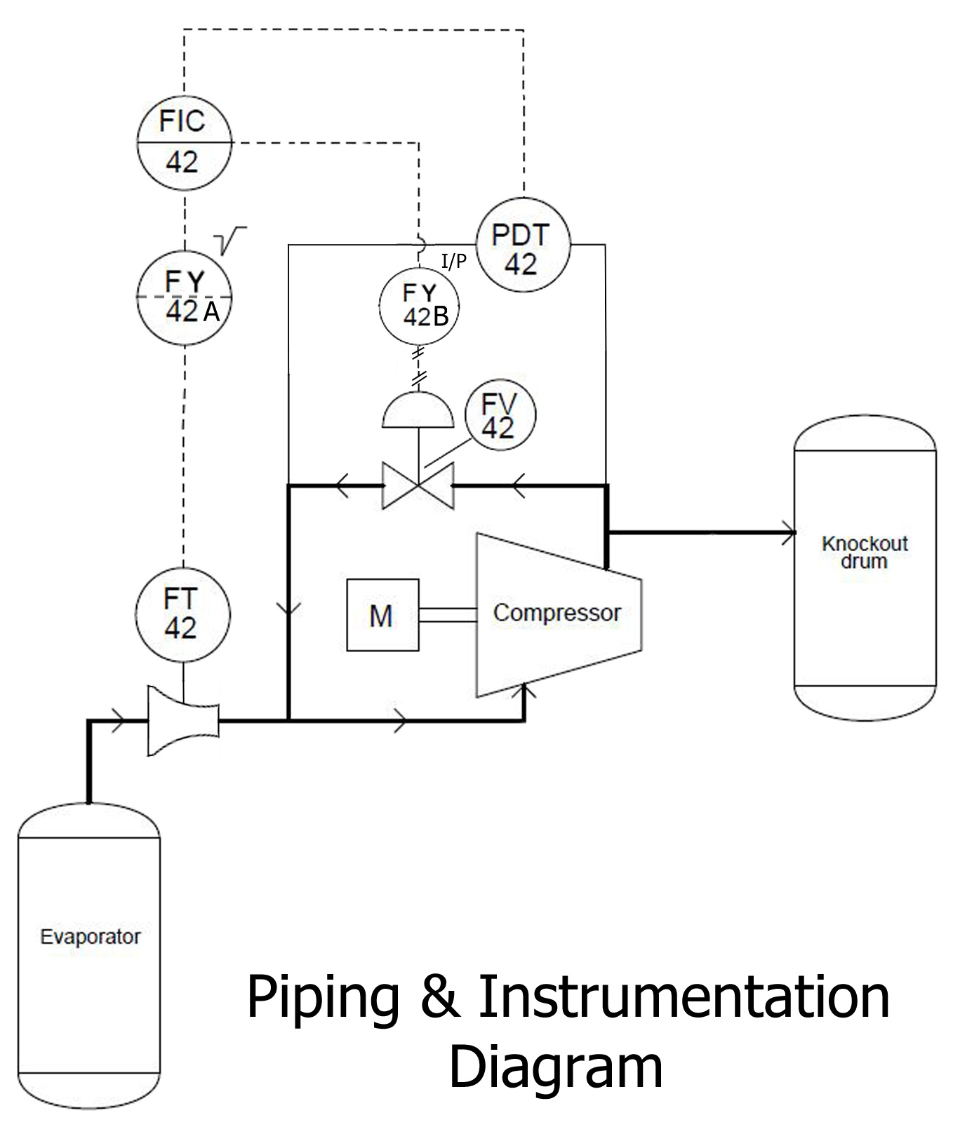
What Is A Pid Drawing - Web the automation, systems and instrumentation dictionary in its 4th edition defines what piping and instrumentation drawing do: Piping and instrumentation diagrams (p&ids) use specific symbols to show the connectivity of equipment, sensors, and valves in a control system. P&id (piping and instrumentation diagram or drawing) is a technical drawing used in process engineering. Web a piping and instrumentation diagram (p&id or pid) is a detailed diagram in the process industry which shows the piping and process equipment together with the instrumentation and control devices. Piping & instrumentation diagram explained. Process piping, sizes and identification. Web a piping and instrumentation diagram, also called p&id, is a diagram used to show a graphical display of a complete system. P&id is later used for assistance for construction of the. Web piping and instrumentation diagram (p&id) is a drawing elaborating the details of piping and instrumentation of a processing plant, developed at the design stage. They offer a detailed overview of the process flow, including equipment, valves, and instrumentation, crucial for design and operational. This information is displayed in the areas surrounding the graphic portion of the drawing. A p&id uses simple graphics to represent complex processes and convey the flow of material through a process. A piping and instrumentation diagram (p&id) is a comprehensive schematic that illustrates the functional relationship of piping, instrumentation, and system equipment components within a process plant. It shows. P&ids are used to develop guidelines and standards for facility operation. The mechanical and electrical details of a given system or process, A piping and instrumentation diagram (p&id) is a comprehensive schematic that illustrates the functional relationship of piping, instrumentation, and system equipment components within a process plant. Web a piping and instrumentation diagram, also called p&id, is a diagram. Mechanical equipment with names and numbers. Want to make a p&id of your own? Web piping and instrumentation diagram (p&id) is a drawing elaborating the details of piping and instrumentation of a processing plant, developed at the design stage. When you have the right tools on hand, it’s time to begin. Web a piping and instrumentation diagram, or p&id, shows. P&id is later used for assistance for construction of the. P&id drawing is a schematic representation of instrumentations, control systems, and pipelines used in any process development plant. It is also called as mechanical flow diagram (mfd). Web piping and instrumentation diagram (p&id) is a drawing elaborating the details of piping and instrumentation of a processing plant, developed at the design stage. It’s most commonly used in the engineering field. Web the automation, systems and instrumentation dictionary in its 4th edition defines what piping and instrumentation drawing do: Web a process and instrumentation diagram (p & id) shows the process flow and interconnection of process equipment which is used control a process. When you have the right tools on hand, it’s time to begin. This information is displayed in the areas surrounding the graphic portion of the drawing. It uses symbols to represent process equipment such as sensors and controllers. P&ids are foundational to the maintenance and modification of the process that it graphically represents. You may want to review a p&id symbols legend to ensure that you’re using the correct shapes in an appropriate context. Web how to read p&id drawings? Web what is p&id? Web what is a p&id drawing? A p&id uses simple graphics to represent complex processes and convey the flow of material through a process.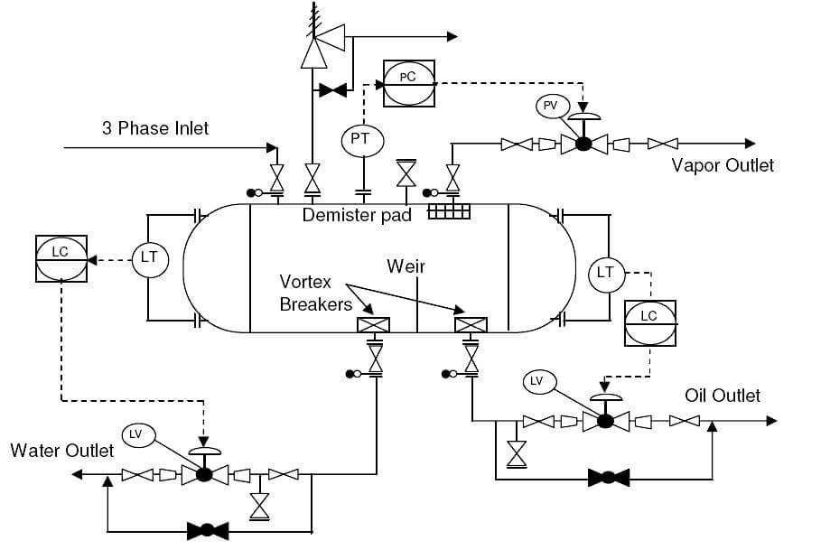
What is Piping and Instrumentation Diagram (P&ID) ? Inst Tools

How to Read and Interpret Piping and Instrumentation Diagrams (P&ID
What is P&ID? (Piping and Instrumentation Diagram)? Synergy Codes
A Through Knowledge Of The Information Presented In The Title Block, The Revision Block, The Notes And Legend, And The Drawing Grid Is Necessary Before A Drawing Can Be Read.
P&Ids Are Used To Develop Guidelines And Standards For Facility Operation.
357K Views 3 Years Ago Basic Instrumentation Through.
It Shows The Equipment Used In The Process, And All Of The Signals Required To Measure And Control The Process.
Related Post: