What Are Engineering Drawings
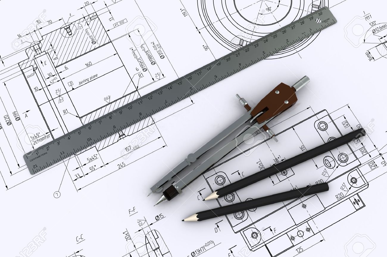
What Are Engineering Drawings - Web as we already discussed in introduction to the engineering drawing, engineering drawing is a unified language that engineers use to communicate. Various symbols and abbreviations in engineering drawings give you information about the dimensions, design, and materials used. We will treat “sketching” and “drawing” as one. “drawing” usually means using drawing instruments, from compasses to computers to bring precision to the drawings. One can pack a great deal of information into an isometric drawing. The purpose is to convey all the information necessary for manufacturing a product or a part. The three standard views are the top, front, and right side. 1.2 historical background and evolution. “sketching” generally means freehand drawing. It makes use of symbols that are standardized to convey precise information to its global reader. Basically, this type of drawing aims at clearly capturing all the geometric features of products and their. Web engineering drawings are key tools that engineers use to communicate, but deciphering them isn’t always straightforward. This is just an introduction. One can pack a great deal of information into an isometric drawing. 1.2 historical background and evolution. Web just as an architectural drawing or blueprint shows you how to construct a building, an engineering drawing shows you how to manufacture a specific item or product. Web explore the three primary types of engineering drawings: Web an engineering drawing (also named as mechanical drawing, manufacturing blueprints, drawings, dimensional prints, and more) refers to one of the technical drawings,. The rules for creating engineering drawings (communication) are defined by a standards organization (for example, iso and asme ). Web a technical drawing created in autocad. One of the best ways to communicate one’s ideas is through some form of picture or drawing. Various symbols and abbreviations in engineering drawings give you information about the dimensions, design, and materials used.. It is the universal “engineering technology language” in the world. Web an engineering drawing is a subcategory of technical drawings that show the shape, structure, dimensions, tolerances, accuracy and other requirements needed to manufacture a product or part. Correctly creating and reading engineering drawings is an essential ability for engineering technicians. 1.4 types of engineering drawing: Web an engineering drawing is a type of technical drawing that is used to convey information about an object. It has its unique syntax and lexicon. The glass box projections produced six views: One of the best ways to communicate one’s ideas is through some form of picture or drawing. These drawings are essentially the blueprints or plans for manufacturing a wide array of products and structures. Web an engineering (or technical) drawing is a graphical representation of a part, assembly, system, or structure and it can be produced using freehand, mechanical tools, or computer methods. The purpose is to convey all the information necessary for manufacturing a product or a part. Web engineering drawings (aka blueprints, prints, drawings, mechanical drawings) are a rich and specific outline that shows all the information and requirements needed to manufacture an item or product. The purpose of this guide is to give you the basics of engineering sketching and drawing. Engineering drawings use standardised language and symbols. “drawing” usually means using drawing instruments, from compasses to computers to bring precision to the drawings. It is more than simply a drawing, it is a graphical language that communicates ideas and information.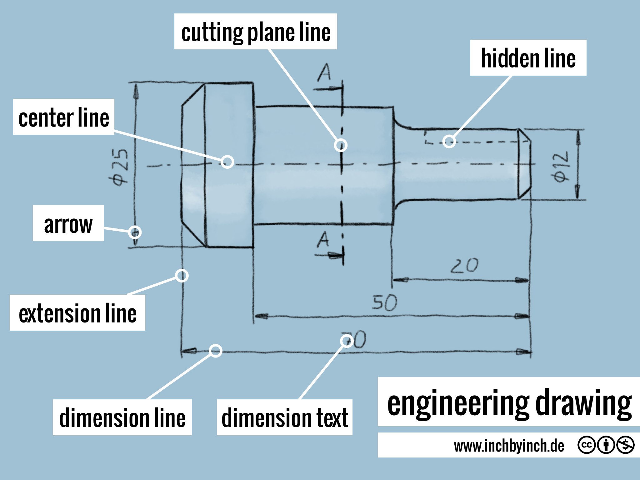
INCH Technical English engineering drawing
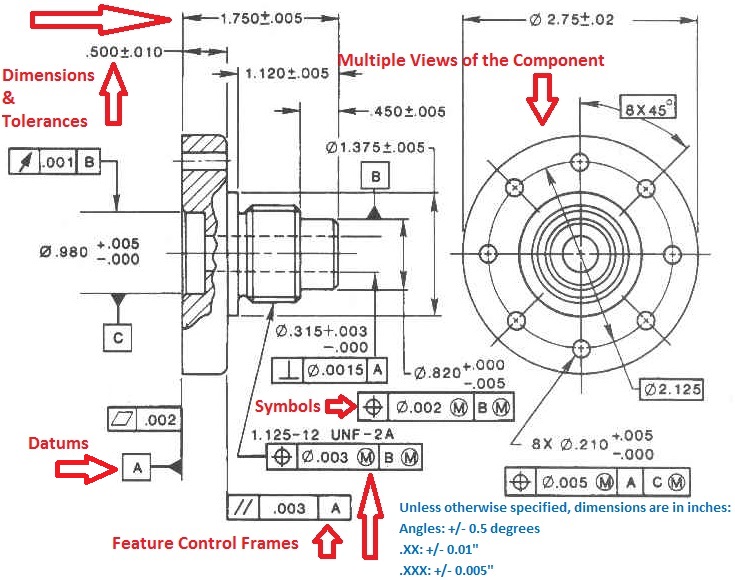
Engineering Drawings & GD&T For the Quality Engineer
Engineering Drawing A Science or Art RRCE
This Makes Understanding The Drawings Simple With Little To No Personal Interpretation Possibilities.
Usually, A Number Of Drawings Are Necessary To Completely Specify Even A Simple Component.
By Definition, A Technical Drawing—Also Known As An Engineering Drawing—Is A Detailed, Precise Diagram Or Plan That Conveys Information About How An Object Functions Or Is Constructed.
A Common Use Is To Specify The Geometry Necessary For The Construction Of A Component And Is Called A Detail Drawing.
Related Post: