Welding Callouts On Drawings
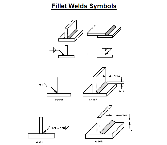
Welding Callouts On Drawings - It locates the flag at the original site in the country where the project demands. Web how to read a weld symbol. Web about welding symbols in drawings. The specific system will be indicated on the plans, and both systems will not be included on one drawing. The arrow connects the weld callout to one side of the joint to be welded. Symbols shown above are typical for all welded joints of similar construction unless otherwise specified. 1” stud welds on the arrow side, 2” pitch, 20 total studs. The standard creo welding symbol libraries provide general ansi and iso welding symbols. 1/4” stud welds on the arrow side with a. The arrow line is connected to a leader line which is intersected with a horizontal reference line. Learn how to interpret and use weld callout symbols and notations effectively in your projects. This was a very basic introduction to weld symbols. These sit on the arrow or the other side of the reference line, indicating the type of weld.; Web the two drawing systems. The arrow line is connected to a leader line which is intersected with. In the space below draw a symbol for the following: You can see different fillet, plug, spot, and many other kinds of weld types. 3/16” spot weld on the arrow side, ground flush, a pitch of 2”, and 8 total welds. Symbols shown above are typical for all welded joints of similar construction unless otherwise specified. Here we will introduce. The software supports ansi, iso, gost, and jis weld symbol libraries. Web basic weld symbols. In the space below draw a symbol for the following: There are a lot of processes in the welding industry, in order to streamline the call out of these there are letter designations for them. Web drawing callout for weld symbols 2.1.1. The purpose of this page is to introduce you to the common symbols and their meaning. Welding symbols are used to indicate desired welding & brazing details on the fabrication drawings. You can easily customize and create new welding symbols to. Base system a is distinguished by the dash lines underneath the reference line. It is essential that the 'rules' of the standard used are correctly applied by drawing office personnel. There are two systems the base welding symbol comes in, and they are each interpreted differently. 1.1 engineering specification for weld callouts document #. You can use the weld symbol tool to add weld symbols to assemblies, drawings, vertices, and edges or faces of parts. Basic forms of weld seam overlap. However, it is also important that shop floor personnel are able to read and understand the details of weld symbols. Resistance seam weld with no side significance, 8” pitch, 16” length. The specific system will be indicated on the plans, and both systems will not be included on one drawing. You can see different fillet, plug, spot, and many other kinds of weld types. Web when welds are specified on engineering and fabrication drawings, a cryptic set of symbols issued as a sort of shorthand for describing the type of weld, its size, and other processing and finishing information. Web detailed part drawings may contain many welding symbols. You can also find a tail at the opposite end of the reference line which then branches off in two different directions.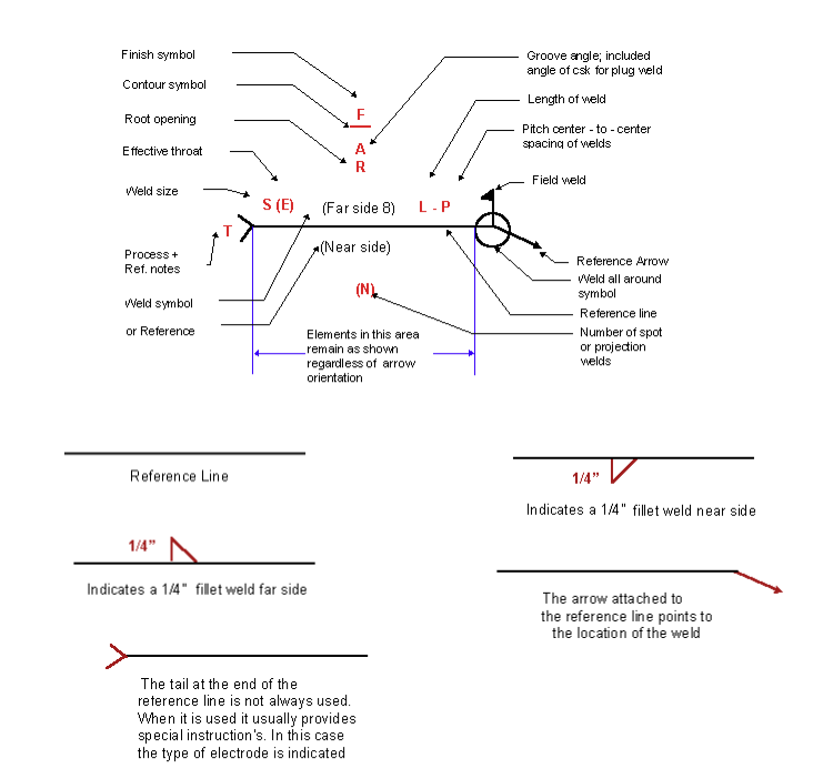
Understanding the Welding Symbols in Engineering Drawings Safe Work

Understanding the Basic Welding Symbols
Understanding the Welding Symbols in Engineering Drawings Safe Work
The Standard Creo Welding Symbol Libraries Provide General Ansi And Iso Welding Symbols.
Web 11 Process And Method.
The Dialog Box Opens When You Place A Welding Symbol.
The Software Supports Ansi, Iso, Gost, And Jis Weld Symbol Libraries.
Related Post: