Volt Ohm Meter Drawing
Volt Ohm Meter Drawing - Direct current (dc) chapter 8 dc metering circuits. Web simple attach the test leads to the dut (device under test) and read the voltage/current/resistance from the screen. Web learn how to measure voltage and current in electrical circuits using voltmeters and ammeters. Though mechanical ohmmeter (resistance meter) designs are rarely used today, having largely been superseded by digital instruments, their operation is nonetheless intriguing and worthy of study. The ohmmeter displays the calculated resistance value on a calibrated scale or digital readout. Discover why voltmeters are connected in parallel and ammeters in series. But to measure greater levels of voltage, something more is needed. Sam goldheart (and 3 other contributors) create a guide. Web this particular multimeter has several basic voltage measurement ranges: Thus, the ratio of voltage to current is the resistance of the component or circuit. With the use of the voltage range extender unit at the top of the multimeter,. When measuring voltage, for example, the multimeter detects the potential electrical difference between two points and displays this as a voltage reading. The vom has the advantages of being inexpensive and portable. The unit shown above is typical of a handheld analog multimeter, with ranges. Ohmmeter is used to directly measure resistance of a device, element, circuit or any portion thereof. With the use of the voltage range extender unit at the top of the multimeter,. The various multimeter symbols include: Web a digital multimeter works by measuring the electrical properties of a circuit and converting these measurements into a digital readout. 1.) or a. Web electrical instruments & measurement / april 11, 2023 / electrical instruments. One type of ohmmeter is the series ohmmeter, so called because the meter movement is in series with the source of emf and the unknown resistance. R = resistance in ohms v = voltage in volts i = current in amperes. Ohmmeter is used to directly measure resistance. With the use of the voltage range extender unit at the top of the multimeter,. R = resistance in ohms v = voltage in volts i = current in amperes. Direct current (dc) chapter 8 dc metering circuits. If all we wanted was a meter that could measure 1/2 of a volt, the bare meter movement we have here would suffice. Some voms can also measure sound levels (decibels) or other metrics using an appropriate attachment. The various multimeter symbols include: One type of ohmmeter is the series ohmmeter, so called because the meter movement is in series with the source of emf and the unknown resistance. It does, however, usually have a low. This meter is used to determine approximate (not too accurate) resistance of the circuit components. Web simple attach the test leads to the dut (device under test) and read the voltage/current/resistance from the screen. An ohmmeter is an instrument used to measure the resistance. The following is an explanation of the most common multimeter symbols. Thus, the ratio of voltage to current is the resistance of the component or circuit. The internal circuitry of the ohmmeter then calculates the resistance using ohms’s law by dividing voltage by current. As was stated earlier, most meter movements are sensitive devices. Understand the importance of resistance in these devices to ensure accurate readings and prevent damage.![]()
Digital Multimeter for Measuring Electrical Indicators AC DC Voltage
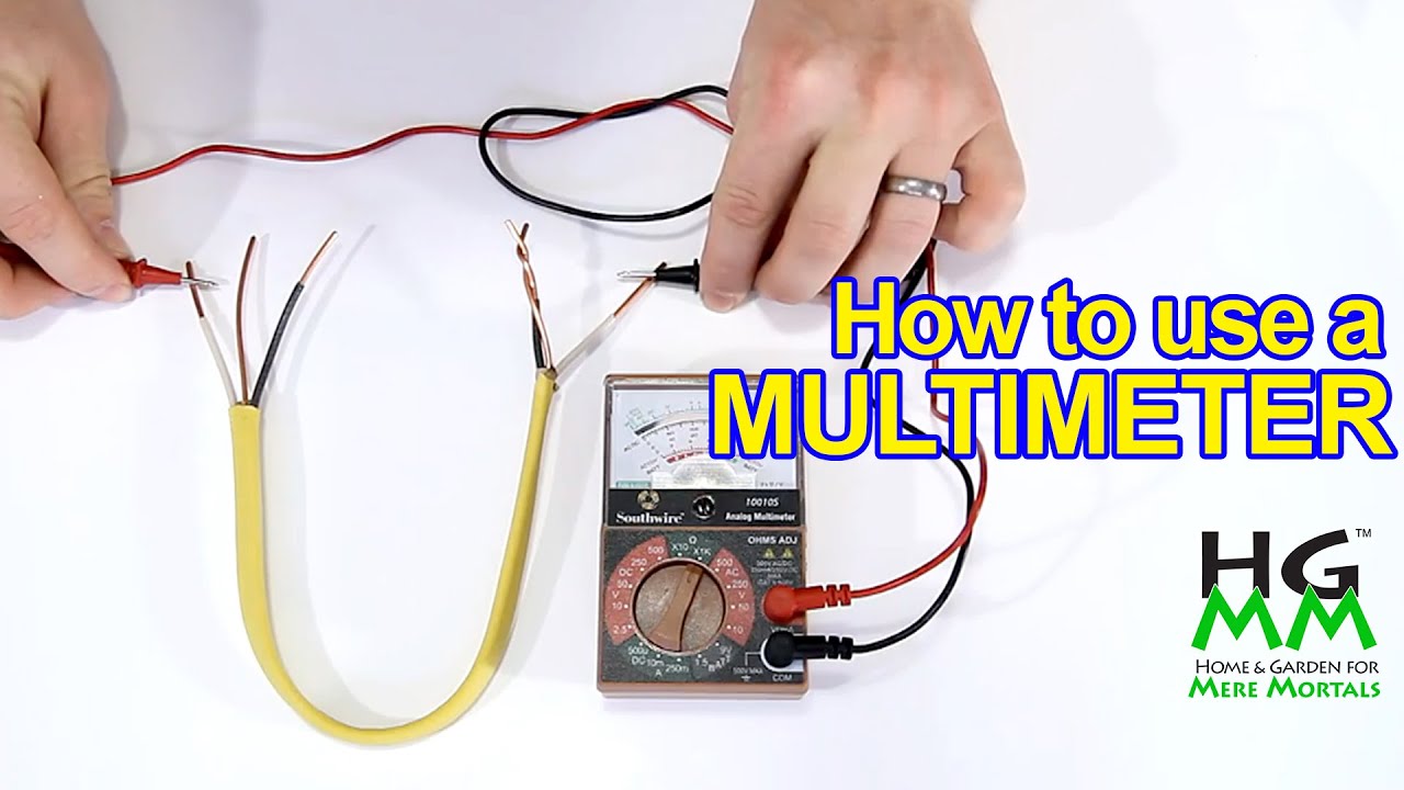
How to use a multimeter or voltmeter Basics you need to know. YouTube

Voltmeter Royalty Free Vector Image VectorStock
Web Using Ohm's Law (E=Ir), We Can Determine How Much Voltage Will Drive This Meter Movement Directly To Full Scale:
Web Schematic Of Volt / Ammeter.
The Normal Practice Is To Provide Several Ranges For Each Function.
2.5 Volts, 10 Volts, 50 Volts, 250 Volts, 500 Volts, And 1000 Volts.
Related Post: