Valve Symbols On Drawings
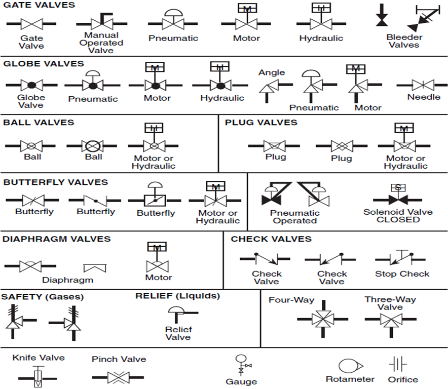
Valve Symbols On Drawings - These symbols can represent actuators, sensors, and controllers and may be. In such cases, information concerning the valve type may be conveyed by the component Web there's a huge variety of symbols, depending on industry and manufacturer, so we've created this guide to feature the most popular p&id symbols supported within our p&id software and is standardized for best practice across the industry. Web type of valve employed depends on nature of fluid, flow control required, operating pressure and temperatures as well as surround atmosphere. Components that connect sections of piping, change the direction of flow, or enable branching, including elbows, tees, reducers, and flanges. Here is a list of symbols for various types of valves used in process industry. Engineers use control valve symbols to identify the type of control valve they want to specify for a given application. Web move a disc, or plug into or against an orifice (for example, globe or needle type valve). Web valve symbols are graphical representations of various types of valves used in piping and instrumentation diagrams (p&ids) and other engineering schematics. Web piping and instrumentation diagrams (p&ids) use specific symbols to show the connectivity of equipment, sensors, and valves in a control system. Want to make a p&id of your own? Web a piping and instrumentation diagram (p&id) is a graphic representation of a process system that includes the piping, vessels, control valves, instrumentation, and other process components and equipment in the system. The valve symbols can show you the type, how they operate, and more. Figure 1 shows the symbols that depict. So, to understand a system shown on a process flow diagram (fd) or a piping and instrument diagram (p&id), you must understand the valve symbols. These symbols are standardized by the american society of mechanical engineers (asme) and are used in a variety of industries, including oil and gas, chemical, and manufacturing. Such as ball valve, plug valve, refile valve,. Web valve symbols in process and instrumentation diagrams. Web valve symbols are graphical representations of various types of valves used in piping and instrumentation diagrams (p&ids) and other engineering schematics. In such cases, information concerning the valve type may be conveyed by the component Slide a flat, cylindrical, or spherical surface across an orifice (for example, gate and plug valves).. Web a piping and instrumentation diagram (p&id) is a graphic representation of a process system that includes the piping, vessels, control valves, instrumentation, and other process components and equipment in the system. It's quick, easy, and completely free. Web a valve controls the flow of air or liquid through the piping. Web p&ids include standard symbols that explain: The symbol typically consists of the actual valve symbol, and the actuation method such as pneumatic, hydraulic, or electric. The valve symbols can show you the type, how they operate, and more. So, to understand a system shown on a process flow diagram (fd) or a piping and instrument diagram (p&id), you must understand the valve symbols. The symbols for these components aren’t drawn to scale and aren’t intended to be dimensionally accurate. How do i read valve symbols and p&id diagrams? They include the vessels, piping, control valves, instrumentation, equipment, and other components involved in. In such cases, information concerning the valve type may be conveyed by the component Figure 1 shows the symbols that depict the major valve types. Web valve symbols in process and instrumentation diagrams. Components that connect sections of piping, change the direction of flow, or enable branching, including elbows, tees, reducers, and flanges. Valves are used to control the direction, flow rate, and pressure of fluids. Web what does piping & instrumentation diagram (p& id) imply?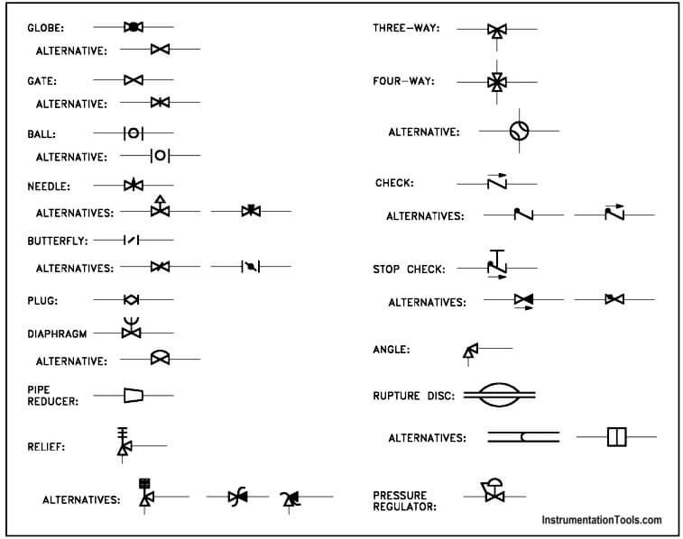
Piping and Instrumentation Symbols Instrumentation Tools

Valves Symbols used in P&ID and Piping Isometric drawings YouTube
Valve Sign Symbols The Engineering Concepts
Slide A Flat, Cylindrical, Or Spherical Surface Across An Orifice (For Example, Gate And Plug Valves).
These Symbols Can Represent Actuators, Sensors, And Controllers And May Be.
Web Valve Symbols Valves Are Used To Control The Direction, Flow Rate, And Pressure Of Fluids.
These Symbols Are Standardized By The American Society Of Mechanical Engineers (Asme) And Are Used In A Variety Of Industries, Including Oil And Gas, Chemical, And Manufacturing.
Related Post: