Thread Callout On Drawing
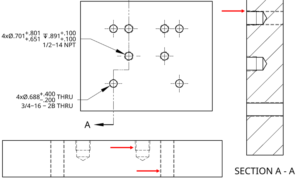
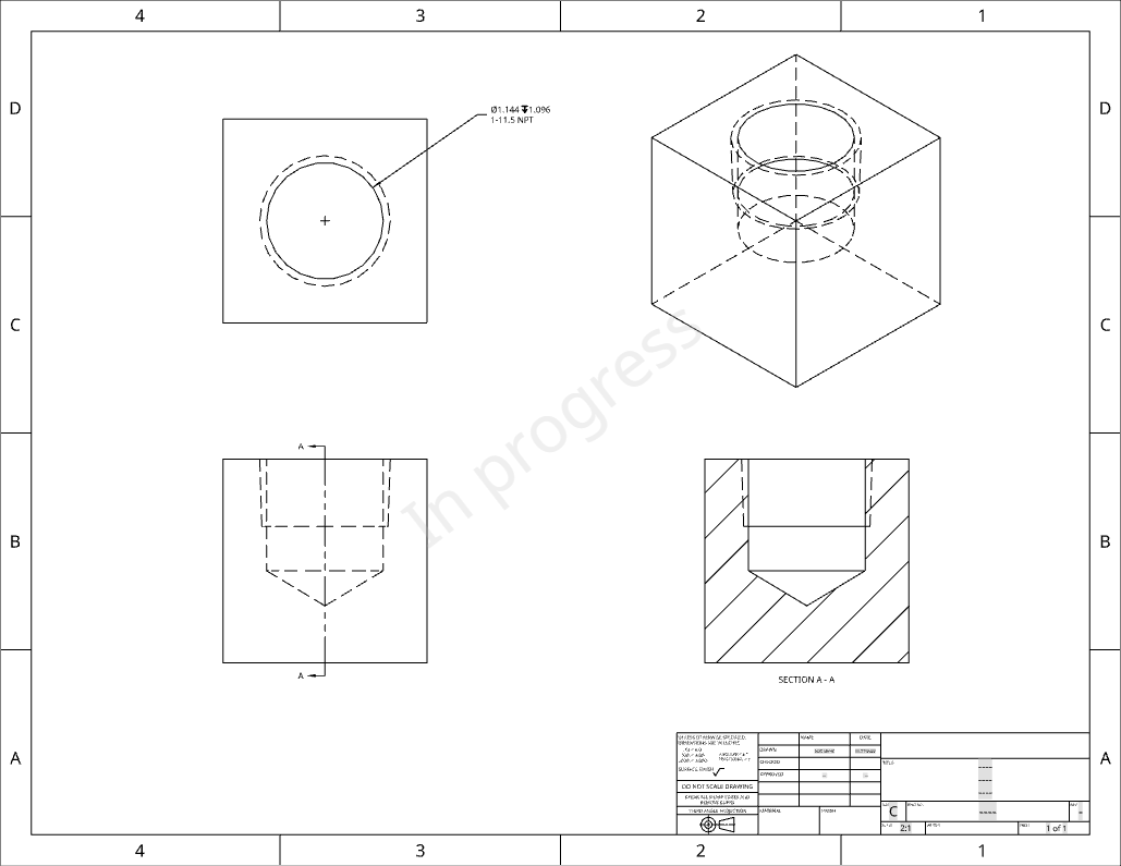
Thread Callout On Drawing - Steps creating a hole or thread callout: You have to look for a label on the packaging or on the shelf where you bought the screw. Web when a thread is called out on a drawing, the information will include the nominal size (diameter) and may include either the threads per inch or thread pitch, depending on whether inch or metric threads are being used. Using callouts for american screws. Annotation standardization is provided by the asme y14 series of standards. We have these diameters published in our engineering design manual, but i have not been able to locate their source. Specify threads on a 2d drawing with a thread specification callout (aka thread hole callout) for metric sizes, specify size with the thread pitch (diameter x pitch in mm); Here are a few important things to remember when specifying threads: It is usually not printed on the screw. Web forms of screw threads on engineering drawings and related documentation. Look for a label with the callout printed on it. Web tips for threaded hole callouts. A thread note must be included on all threaded parts, with a leader line to the external thread or to an internal thread in the circular view. Web thread callout in technical drawings; Here are a few important things to remember when specifying threads: Annotation standardization is provided by the asme y14 series of standards. Web tips for threaded hole callouts. Utilizing established symbolic callouts and terms as defined in. Using callouts for american screws. Web threads are only symbolically represented on drawings; In the above tap hole callout, we have given two callouts to understand it in both metric and inch systems. Drag to place the callout. Steps creating a hole or thread callout: Inch thread and metric thread callout on the engineering drawing. Therefore, thread notes are needed to provide the required information. Web when a thread is called out on a drawing, the information will include the nominal size (diameter) and may include either the threads per inch or thread pitch, depending on whether inch or metric threads are being used. Here are a few important things to remember when specifying threads: Specify threads on a 2d drawing with a thread specification callout (aka thread hole callout) for metric sizes, specify size with the thread pitch (diameter x pitch in mm); There are 3 parts for each callout. Annotation standardization is provided by the asme y14 series of standards. Web forms of screw threads on engineering drawings and related documentation. We have these diameters published in our engineering design manual, but i have not been able to locate their source. It will also define the standard methods of specifying threads and all of their characteristics, including the dimensioning of thread characteristic such as length of incomplete threads, etc. In the above tap hole callout, we have given two callouts to understand it in both metric and inch systems. Look for a label with the callout printed on it. This handout will focus on the standards of annotation for fasteners, and hole callouts (local notes). Inch thread and metric thread callout on the engineering drawing. Web tips for threaded hole callouts. A thread note must be included on all threaded parts, with a leader line to the external thread or to an internal thread in the circular view. Web thread callout in technical drawings; Drag to place the callout.
Hole/Thread Callout

Hole/Thread Callout

Using Cosmetic Threads in SOLIDWORKS Parts and Drawings
Therefore, Thread Notes Are Needed To Provide The Required Information.
It Is Usually Not Printed On The Screw.
Web Threads Are Only Symbolically Represented On Drawings;
Utilizing Established Symbolic Callouts And Terms As Defined In.
Related Post: