Symbols On Electrical Drawings
Symbols On Electrical Drawings - The images below show the schematic symbols for wires when they are physically connected in a circuit. These symbols represent components in schematic diagrams. Each symbol represents a specific electrical component or function, allowing professionals to quickly identify and locate key elements within a system. There are some standard symbols to represent the components in a circuits. What are electrical and electronics symbols? Represented by a line with a gap or by various types of. The most fundamental of circuit components and symbols! An electric planer is an instrument that helps to shave and shape wood. You can depict a complex electrical circuit with the standard and simplified electrical symbols. Commonly used abbreviations in optical, logical and microprocessor circuits component identification abbreviations. Web now that you’re familiar with the common symbols used in schematic diagrams, let’s take a look at how to read wire connections and wire crossings. Represented by a zigzag line; Web electrical systems such as lights, switches, circuit breakers, distribution panels, and fixtures are denoted using various symbols described in legends. These symbols are commonly used in. Web common. One line may even represent multiple conductors with other devices between them. What are electrical and electronics symbols? Connections and network elements power plant electronic devices logic symbols optic fibre symbols telecommunication symbols microwave devices flowchart symbols. Web electrical systems such as lights, switches, circuit breakers, distribution panels, and fixtures are denoted using various symbols described in legends. These symbols. Web you will learn how to define the symbols that should be used according to the type of electrical diagram, clarify the choice of a symbol that should be used on a plan, specify why representation standards are used, and associate a type of standard with a type of symbol through the use of this handbook. Web common electrical symbols. Web helpful tools for architects and building designers. Web electrical systems such as lights, switches, circuit breakers, distribution panels, and fixtures are denoted using various symbols described in legends. Web electrical symbols are visual representations in electrical drawings and diagrams to convey information about components, devices, and connections within a circuit or system. The basics of electrical symbols. Represented by two parallel lines; Lucidchart has all the symbols you'll need for your circuit diagram. Electrical symbols or electronic circuits are virtually represented by circuit diagrams. Electrical plan symbols used in electrical drawings, including power, lighting, security, fire alarm, and communications symbols. These symbols allow professionals to read and interpret circuit diagrams, troubleshoot issues, and design new circuits. Commonly used abbreviations in optical, logical and microprocessor circuits component identification abbreviations. A function block diagram, although it can represent the connection of physical devices, is meant to show a logical connection. Understanding electrical symbols is a foundational aspect of architectural design and planning. Represented by a line with a gap or by various types of. An electric planer is an instrument that helps to shave and shape wood. The most fundamental of circuit components and symbols! Represented by a zigzag line;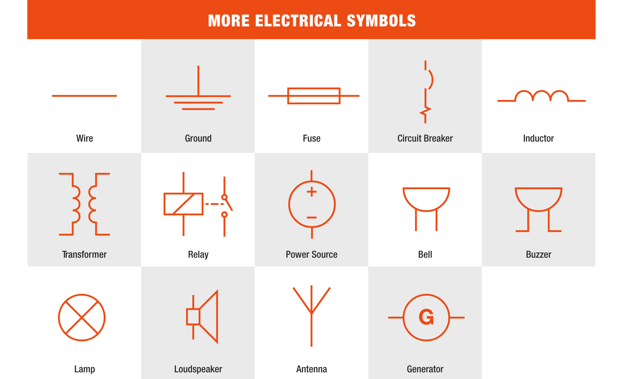
How to Read Electrical Symbols The Home Depot
Electrical Symbols Electrical Drawing Symbols Electrical Academia
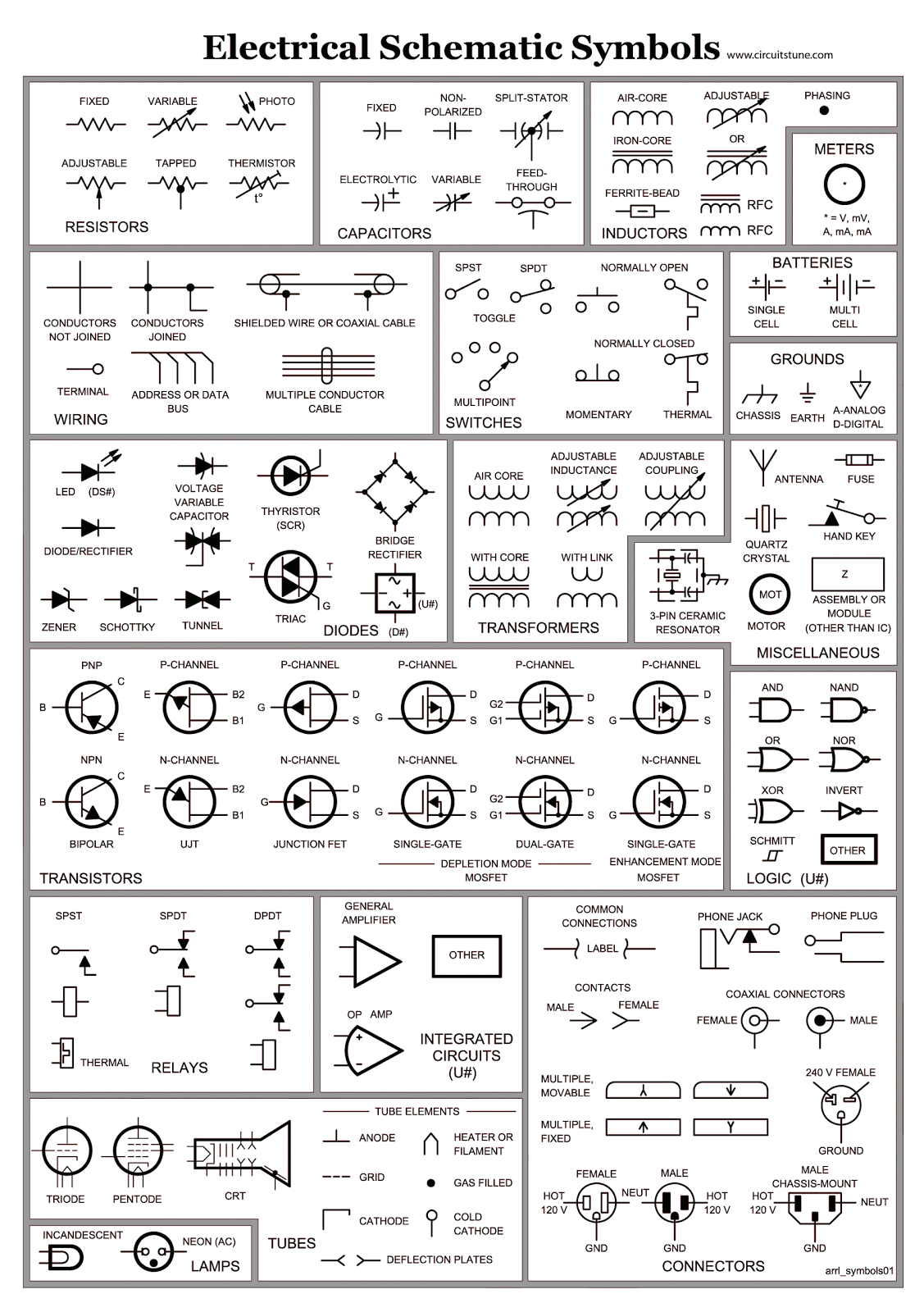
Electrical Schematic Symbols CircuitsTune
Web Now That You’re Familiar With The Common Symbols Used In Schematic Diagrams, Let’s Take A Look At How To Read Wire Connections And Wire Crossings.
What Are Electrical And Electronics Symbols?
This Article Gives Some Of The Frequently Used Symbols For Drawing The Circuits.
Whether You Are A Novice Or A Professional Engineer, These Basic Symbols Can Help Create Accurate Electrical And Circuit Diagrams In Minutes.
Related Post: