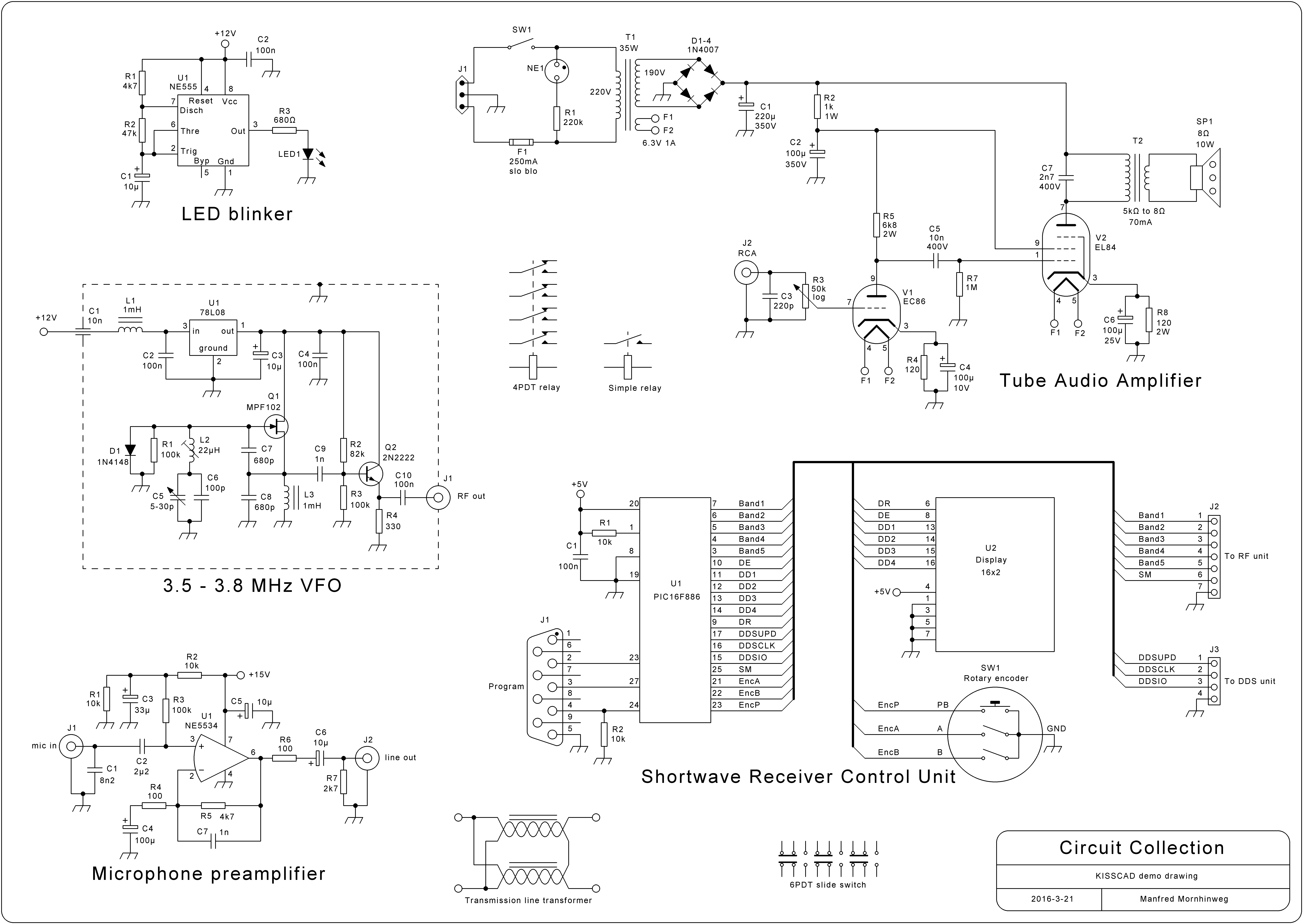
Schematics Drawing
Schematics Drawing - Web a schematic, also known as a circuit diagram, is a visual representation of an electronic circuit. With symbols ranging from amplifiers to vacuum tubes, as well as the ability to build custom symbols, you are able to design nearly any circuit. Create your own custom symbols or use some of the thousands found in the official kicad library. Draw.io can import.vsdx, gliffy™ and lucidchart™ files. Kicad's schematic editor supports everything from the most basic schematic to a complex hierarchical design with hundreds of sheets. Easy to create and customize. Web a schematic, or schematic diagram, is a designed representation of the elements of a system using abstract, graphic symbols rather than realistic pictures. One animated circuit is worth a thousand equations and diagrams. Millions of photos, icons and illustration. The tool includes a comprehensive electronic symbol library and an integrated digikey component catalog that allows for a. Web free circuit diagram maker. Millions of photos, icons and illustration. Analog & digital circuit simulations in seconds. Web a schematic diagram is a visual representation of a project plan that is prepared using lines and generic icons to keep the drawing extremely simple and easily understandable. Web create your first circuit diagram from a template, blank canvas, or by. Create diagrams visually by placing components with your cursor. Draw.io has everything you expect from a professional diagramming tool. The ability to read electrical schematics is a really useful skill to have. Draw.io can import.vsdx, gliffy™ and lucidchart™ files. Don't worry about licenses or platforms, it just works. Kicad's schematic editor supports everything from the most basic schematic to a complex hierarchical design with hundreds of sheets. The tool includes a comprehensive electronic symbol library and an integrated digikey component catalog that allows for a. Understanding how to read and follow schematics is an important skill for any electronics engineer. Schematics are our map to designing, building, and. A schematic is defined as a picture that shows something in a simple way, using symbols. Use schematic symbols to layout the components of your circuit and make electrical connections. Create your own custom symbols or use some of the thousands found in the official kicad library. Unlike a pictorial diagram, a schematic doesn’t aim to represent the physical layout of the components. Published on january 29, 2019. With symbols ranging from amplifiers to vacuum tubes, as well as the ability to build custom symbols, you are able to design nearly any circuit. No login or registration required. Schematics are our map to designing, building, and troubleshooting circuits. Light up your creativity and speed up your workflow with our free, online circuit diagram maker. Web draw.io is free online diagram software. They’re like a map for building or troubleshooting circuits, and can tell you almost everything you need to know to understand how a circuit works. Animations of voltages, currents, and charges are displayed right on top of schematic, providing great insight into circuit operation. Analog & digital circuit simulations in seconds. Draw.io has everything you expect from a professional diagramming tool. It uses standardized symbols to represent electronic components and shows how these components are connected to form a circuit. The tool includes a comprehensive electronic symbol library and an integrated digikey component catalog that allows for a.
How to Read a Schematic SparkFun Learn

free software to draw schematic diagrams Wiring Diagram and Schematics

How to Draw schematics Circuit and diagrams / electrical Drawing part
You Can Use It As A Flowchart Maker, Network Diagram Software, To Create Uml Online, As An Er Diagram Tool, To Design Database Schema, To Build Bpmn Online, As A Circuit Diagram Maker, And More.
Add Shapes, Connecting Lines, And Text To Make Your Diagram More Robust.
Web Basic Electrical And Electronic Graphical Symbols Called Schematic Symbols Are Commonly Used Within Circuit Diagrams, Schematics And Computer Aided Drawing Packages To Identify The Position Of Individual Components And Elements Within A Circuit.
Web Circuit Schematics Are The Bridge Between Conceptual Electrical Design And Physical Realization Of A Printed Circuit Board Assembly, Or Pcba.
Related Post: