Ref Dimension On Drawing
Ref Dimension On Drawing - Web to add a reference dimension: Dimension preview in creo cad software. You can dimension to a silhouette edge. Web engineering educator academy. Point to the silhouette edge, and when the pointer appears, click to dimension. The use of “ref” or enclosing the dimension inside parentheses are by far the most common notations used. Click smart dimension (dimensions/relations toolbar) or click tools > dimensions > smart. There is no gd&t symbol for a reference measuring. Linear dimension between two elements. Web basic requirements for dimensioning in part drawings. Dimensions shall be selected and arranged to suit the function and mating relationship of a part and shall not be subject to more than one interpretation. To create a new reference dimension. Linear dimension between two elements. Click sketch > reference and select the entities to define the dimension. Web access the dimension dialog. Methods and steps for dimensioning parts. Click the arrow to collapse or expand this section. This means you can ensure your drawings are as clear and readable as possible. These are called out on. Web a reference dimension is a dimension on an engineering drawing provided for information only. You can dimension to a silhouette edge. This means you can ensure your drawings are as clear and readable as possible. A reference dimension is a repeat of a dimension or is derived from other values on the drawing or related drawings. Linear dimension between two elements. Reference size are shown on a drawing as a. To create a new reference dimension. Web we’ll review brief descriptions of each and then dive deeper into basic dimension. In a drawing view, click the items you want to dimension. Angular dimension between three points. Web a reference dimension is a dimension on an engineering drawing provided for information only. Basic dimensions are enclosed in a rectangular box & have no tolerance. In a drawing view, click the items you want to dimension. Linear dimension between two elements. Reference dimensions are provided for a variety of reasons and are often an accumulation of other dimensions that are defined elsewhere [2] (e.g. Web engineering educator academy. Web access the dimension dialog. Reference size are shown on a drawing as a. Dimension annotation of various small holes on parts. These are called out on. In many instances, they make a representation better to understand. You can dimension to a silhouette edge.
How to Create Dimensions in AutoCAD AutoCAD Dimensioning Tutorial

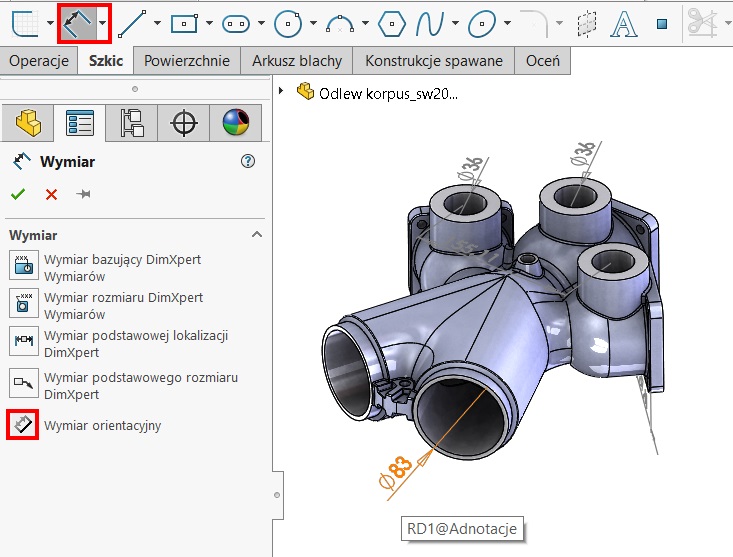
reference dimension, how to insert and use of SOLIDWORKS BLOG
![Dimensioning Its Types, System, Principles. [A Comprehensive Guide].](https://civilseek.com/wp-content/uploads/2018/10/dimensioning.jpg)
Dimensioning Its Types, System, Principles. [A Comprehensive Guide].
Point To The Silhouette Edge, And When The Pointer Appears, Click To Dimension.
As Are Reference Dimensions Shown On A Drawing?
This Means You Can Ensure Your Drawings Are As Clear And Readable As Possible.
Angular Dimension From A Reference Line.
Related Post: