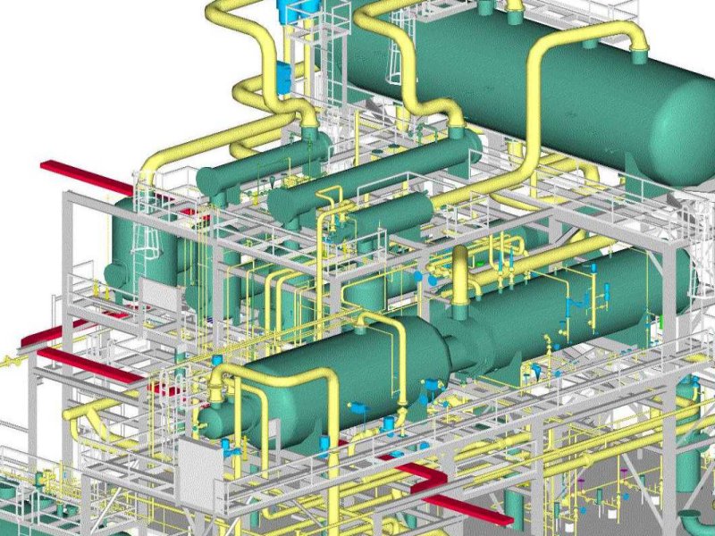
Piping Drawings
Piping Drawings - Web piping isometric is a representation of a single pipe line in a process plant with exact dimensions and bill of material (bom). Piping fabrication work is based on isometric drawings. Web a piping isometric drawing provides all the required information like: Web piping design is a critical discipline in mechanicaal engineering that involves the planning, layout, and specification of the systems used to transport fluids, gases, and other materials in the insdustries and commercial facilities. Reading tips, symbols, and drawing techniques for engineers and piping professionals. The drawing axes of the isometrics intersect at an angle of 60°. Web posted in design engineering. Piping and component descriptions with size, quantity, and material codes. Download and install the 2025.0.1 or newer update. Piping joint types, weld types. Web piping & instrument diagrams: Piping isometric drawing consists of three sections. Each client mandates the drawing numbering to be used. File numbering, which ideally should equate to table 1.2 branch connections instrument and utility air Web various symbols are used to indicate piping components, instrumentation, equipments in engineering drawings such as piping and instrumentation diagram (p&id), isometric drawings, plot. Web piping isometric drawing is an isometric representation of single pipe line in a plant. Reading tips, symbols, and drawing techniques for engineers and piping professionals. Web a piping system drawing may be represented by the following three methods. Web this is a certified workshop! This behavior has been addressed in the 2025.0.1 update. These highly structured drawings provide a comprehensive 3d representation of the arrangement, dimensions, and connections of pipes within a system. These various types of piping drawings in engineering organizations are: It's a simple way of using lines and symbols to tell the story of how liquids and gases move around, and how machines control them. Web a piping isometric drawing. Web of drafting abbreviations used on piping drawings. How to read iso drawings. Web this is a certified workshop! Checkout list of such symbols given below. Web piping and instrument drawings (p&ids) p&ids are usually designed to present functional information about a system or component. File numbering, which ideally should equate to table 1.2 branch connections instrument and utility air Each client mandates the drawing numbering to be used. Piping isometric drawings are detailed technical illustrations that show a 3d view of piping systems. A piping and instrumentation diagram, or p&id, shows the piping and related components of a physical process flow. Web piping design and pipeline engineering refer to the creation and documentation of industry standard layout of pipes, equipment, instruments, and controls. Web piping isometric drawing is an isometric representation of single pipe line in a plant. Web the p&id drawings help them to track the interconnection between the piping and instrumentation and equipment. Web a piping isometric drawing provides all the required information like: Download and install the 2025.0.1 or newer update. A p&id provides the design and construction sequence for the plants for systematic planning of activities. Piping fabrication work is based on isometric drawings.
Piping Drawing at GetDrawings Free download

Piping Design Basics Piping Isometric Drawings Piping Isometrics

How to read piping Isometric drawing YouTube
Piping Joint Types, Weld Types.
Piping And Component Descriptions With Size, Quantity, And Material Codes.
Web P&Id Drawing, Or Piping And Instrumentation Diagrams, Is Like A Special Map That Shows How Pipes And Instruments Work Together In Factories And Plants.
They Serve As A Basis For Studying Different Mechanical And Chemical Steps To Find The Root Cause If Something Goes Wrong.
Related Post: