Piping Drawing Symbols
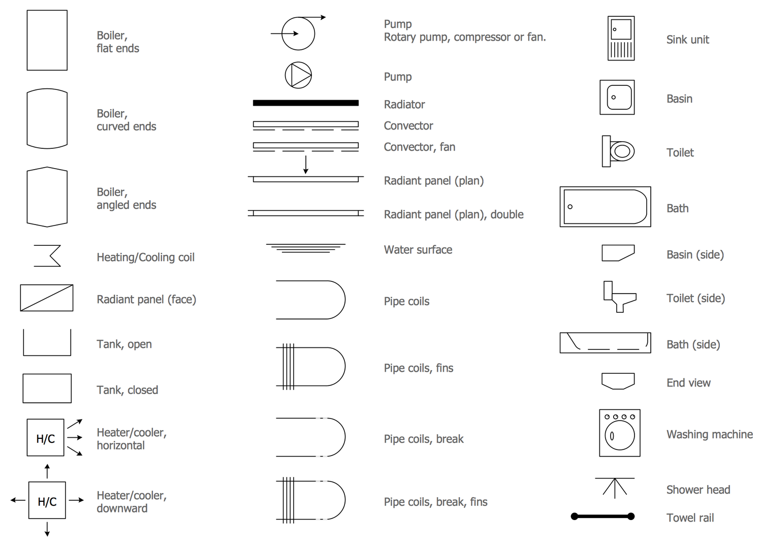
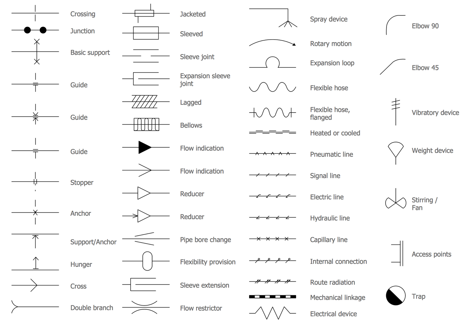
Piping Drawing Symbols - Web in addition to the normal symbols used on p&ids to represent specific pieces of equipment, there are miscellaneous symbols that are used to guide or provide additional information about the drawing. Symbols and conventions are used to represent various piping components and connections, simplifying the drawing while conveying full information. Web standard practice for piping system drawing symbols. Web p&id symbols refer to the standard notations and graphical representations used on piping and instrumentation diagrams (p&ids) to depict the components and systems involved in process flows within a facility. Valves are categorized under the following headings: 2 provides symbols for valves. Web piping and instrument diagram standard symbols detailed documentation provides a standard set of shapes & symbols for documenting p&id and pfd, including standard shapes of instrument, valves, pump, heating exchanges, mixers, crushers, vessels, compressors, filters, motors and connecting shapes. Checkout list of such symbols given below. 1 provides symbols for strainers, separators, and filters. Web various symbols are used to indicate piping components, instrumentation, equipments in engineering drawings such as piping and instrumentation diagram (p&id), isometric drawings, plot plan, equipment layout, welding drawings etc. Web various symbols are used to indicate piping components, instrumentation, equipments in engineering drawings such as piping and instrumentation diagram (p&id), isometric drawings, plot plan, equipment layout, welding drawings etc. Checkout list of such symbols given below. 1 provides symbols for strainers, separators, and filters. Web standard practice for piping system drawing symbols. These symbols are used to indicate the. Web piping and instrument diagram standard symbols detailed documentation provides a standard set of shapes & symbols for documenting p&id and pfd, including standard shapes of instrument, valves, pump, heating exchanges, mixers, crushers, vessels, compressors, filters, motors and connecting shapes. Web p&id symbols refer to the standard notations and graphical representations used on piping and instrumentation diagrams (p&ids) to depict. Web various symbols are used to indicate piping components, instrumentation, equipments in engineering drawings such as piping and instrumentation diagram (p&id), isometric drawings, plot plan, equipment layout, welding drawings etc. The full form of p&id is process and instrumentation diagram. Web piping and instrument diagram standard symbols detailed documentation provides a standard set of shapes & symbols for documenting p&id. Web standard practice for piping system drawing symbols. These symbols are used to indicate the type of connection, the direction of flow, and the size of the pipe. Piping and instrumentation diagram standard notation. Figure 16 lists and explains four. 2 provides symbols for valves. Web various symbols are used to indicate piping components, instrumentation, equipments in engineering drawings such as piping and instrumentation diagram (p&id), isometric drawings, plot plan, equipment layout, welding drawings etc. Web piping symbols, also known as pipe drawings, are a set of symbols used in metal fabrication drawings to represent the various types of pipes and fittings used in industrial piping systems. 1 provides symbols for strainers, separators, and filters. Web knowing the piping drawing symbols will provide various information like: The full form of p&id is process and instrumentation diagram. Halley crast, andrew laskowski, maurice telesford, emily yatc. Web in addition to the normal symbols used on p&ids to represent specific pieces of equipment, there are miscellaneous symbols that are used to guide or provide additional information about the drawing. Piping and pipeline drawing symbols throw lights on the type of joint like buttweld, socket weld, or threaded. Web piping and instrument diagram standard symbols detailed documentation provides a standard set of shapes & symbols for documenting p&id and pfd, including standard shapes of instrument, valves, pump, heating exchanges, mixers, crushers, vessels, compressors, filters, motors and connecting shapes. Isometric drawing piping symbols serve as a ready reference for the type of fittings and components. Globe, angle, check, ball, butterfly, gate, relief, manifolds, control, noise control, and miscellaneous.
What is Piping Isometric drawing? How to Read Piping Drawing? ALL
Piping Isometric Drawing Symbols Pdf at Explore
Piping and Instrumentation Diagram Software
Chemical Process Dynamics And Controls (Woolf) 4:
The Drawing Of Accurate Isometrics During The Engineering Phase Of A Piping System Is Important For A Multitude Of Reasons:
Symbols And Conventions Are Used To Represent Various Piping Components And Connections, Simplifying The Drawing While Conveying Full Information.
Valves Are Categorized Under The Following Headings:
Related Post: