Pipeline Drawing
Pipeline Drawing - These drawings are schematic representations and they would define functional relationships in a piping system. There are usually five types of piping drawings that are prepared to communicate various information in a simple and easy way. Piping and component descriptions with size, quantity, and material codes. Web a piping isometric drawing is a technical drawing that depicts a pipe spool or a complete pipeline using an isometric representation. Web 2.8k views 3 years ago mechanical workshops. Accurate drawing symbols, callouts, precise coordinates, and elevations provide intricate information to the fabricator. The drawing sheet sizes shall be any of the following. Web the main purpose of a piping drawing is to communicate the information in a simple way. Web the process of drafting isometric drawings for a pipeline system involves referencing the arrangements of the pipelines, sections, and elevation drawings during its development. The drawing axes of the isometrics intersect at an angle of 60°. Piping joint types, weld types. Web the main purpose of a piping drawing is to communicate the information in a simple way. Web piping drawings are basically the schematic representations that define functional relationships in a piping or pipeline system. There are usually five types of piping drawings that are prepared to communicate various information in a simple and easy. Accurate drawing symbols, callouts, precise coordinates, and elevations provide intricate information to the fabricator. There are usually five types of piping drawings that are prepared to communicate various information in a simple and easy way. Piping joint types, weld types. Web the main purpose of a piping drawing is to communicate the information in a simple way. The drawings would. Web piping drawings are basically the schematic representations that define functional relationships in a piping or pipeline system. Web a piping isometric drawing provides all the required information like: Web 2.8k views 3 years ago mechanical workshops. Web the main purpose of a piping drawing is to communicate the information in a simple way. Piping and component descriptions with size,. The drawing axes of the isometrics intersect at an angle of 60°. Piping joint types, weld types. Web a piping isometric drawing provides all the required information like: There are usually five types of piping drawings that are prepared to communicate various information in a simple and easy way. Web a piping system drawing may be represented by the following three methods. Web piping drawings are basically the schematic representations that define functional relationships in a piping or pipeline system. Web the main purpose of a piping drawing is to communicate the information in a simple way. This is a certified workshop! Web 2.8k views 3 years ago mechanical workshops. Piping and component descriptions with size, quantity, and material codes. These drawings are schematic representations and they would define functional relationships in a piping system. The drawing sheet sizes shall be any of the following.
Schematic drawing of pipeline in cold regions according to the ground
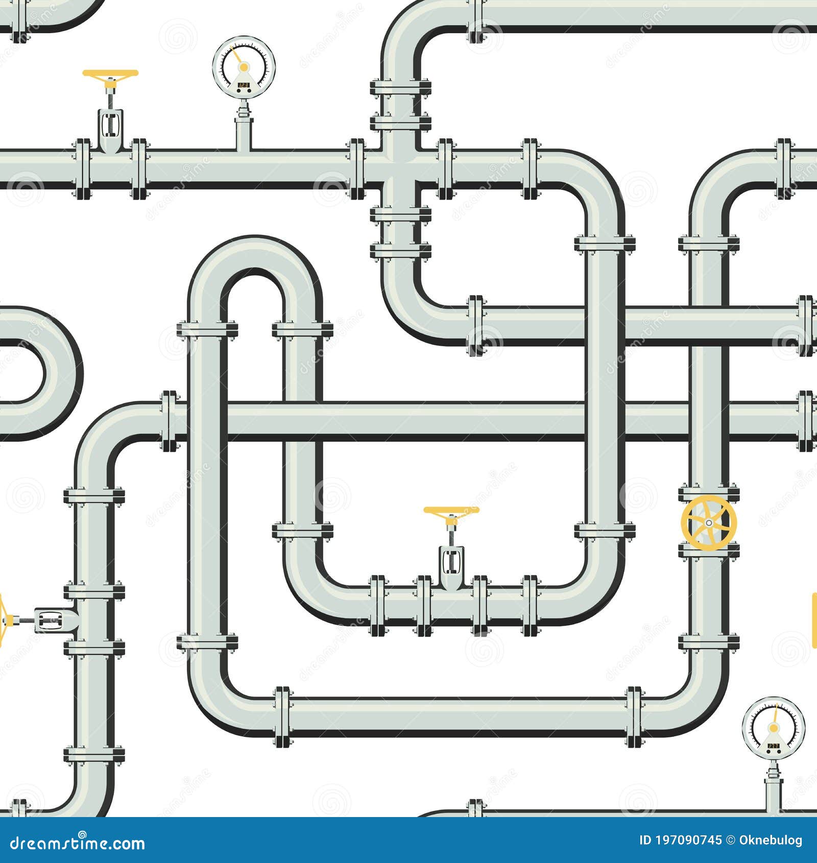
Gas Pipeline Realistic Vector Seamless Pattern in Flat Style Stock
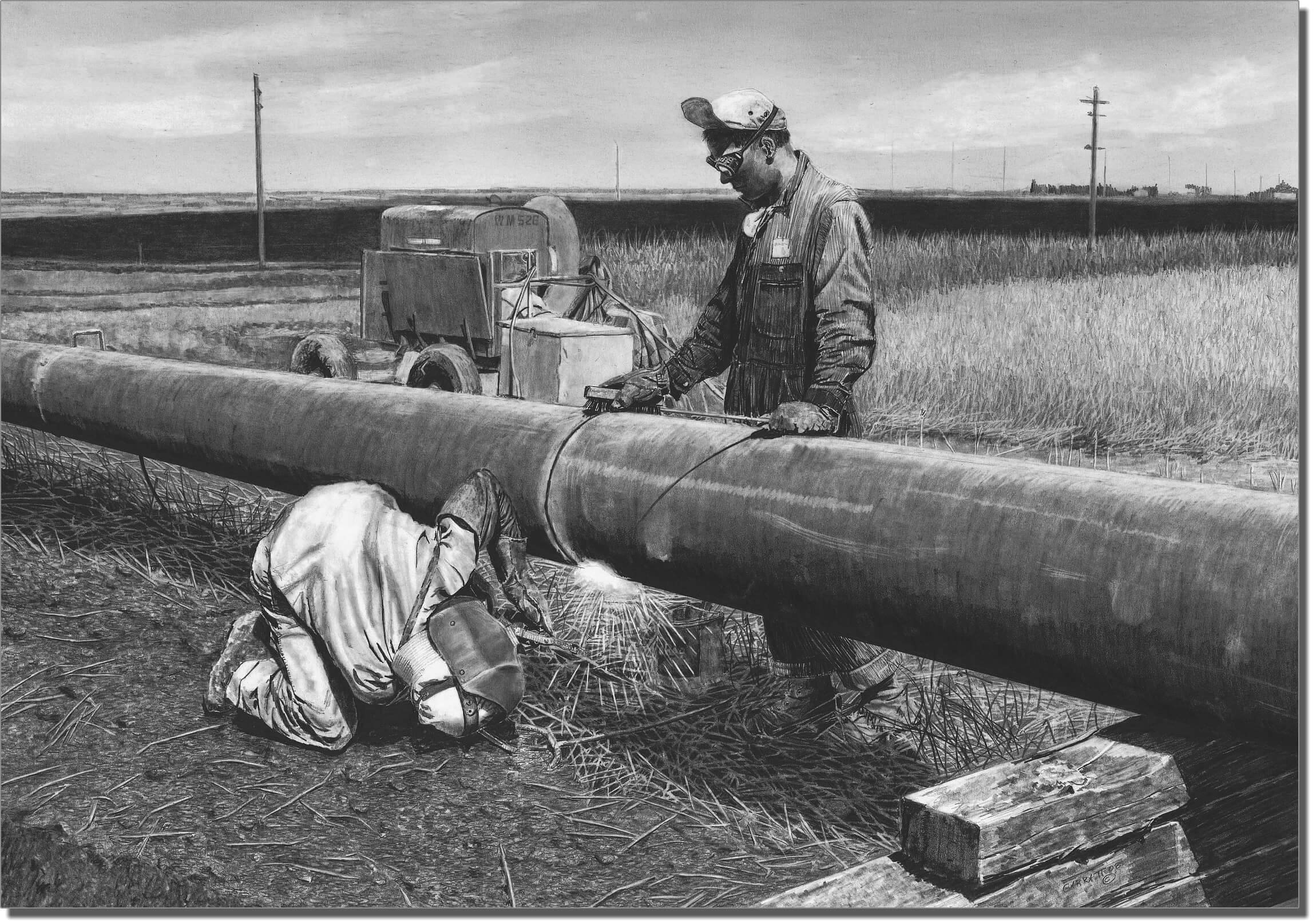
Seam Pipeline Drawing Owen Garratt Pencil Artist
Web A Piping Isometric Drawing Is A Technical Drawing That Depicts A Pipe Spool Or A Complete Pipeline Using An Isometric Representation.
The Drawings Would Help To Speed Up The Fabrication And Erection Work At The Site.
Accurate Drawing Symbols, Callouts, Precise Coordinates, And Elevations Provide Intricate Information To The Fabricator.
Web The Process Of Drafting Isometric Drawings For A Pipeline System Involves Referencing The Arrangements Of The Pipelines, Sections, And Elevation Drawings During Its Development.
Related Post: