Pipe Drawings
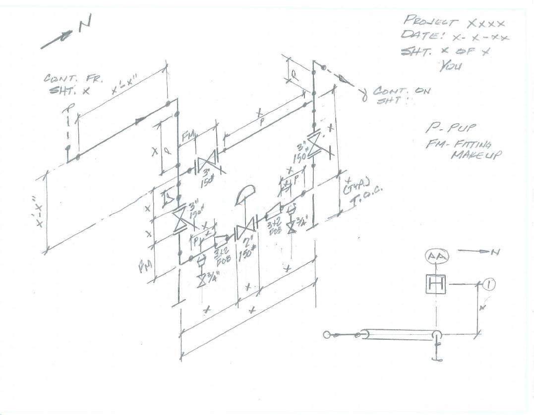
Pipe Drawings - Web piping isometric drawings are rich in information about the various components and connections within a piping system. It is drawn to scale so the relationships of the aforementioned are correctly shown. Web © 2024 google llc. These symbols are used to indicate the type of connection, the direction of flow, and the size of the pipe. Web pipe drawings differ from common blueprints one would see in the construction or welding field. The command scale can be used to. Web various symbols are used to indicate piping components, instrumentation, equipments in engineering drawings such as piping and instrumentation diagram (p&id), isometric drawings, plot plan, equipment layout, welding drawings etc. For this example, the block annosloperatio. Web posted in design engineering. The drawing axes of the isometrics intersect at an angle of 60°. The drawings we often see in these fields would be orthographic views which may include top, front, right side, left side, bottom, and back views depending on what is needed to convey information. Reading tips, symbols, and drawing techniques for engineers and piping professionals. Web master piping isometrics with our comprehensive guide: It is drawn to scale so the relationships. Web © 2024 google llc. Web master piping isometrics with our comprehensive guide: This part of the chapter focuses on the methods for identifying these components and connections accurately: Checkout list of such symbols given below. Web various symbols are used to indicate piping components, instrumentation, equipments in engineering drawings such as piping and instrumentation diagram (p&id), isometric drawings, plot. There are usually five types of piping drawings that are prepared to communicate various information in a simple and easy way. Web piping symbols, also known as pipe drawings, are a set of symbols used in metal fabrication drawings to represent the various types of pipes and fittings used in industrial piping systems. This part of the chapter focuses on. Discover the essentials of piping isometrics, including how they simplify complex piping systems for construction, maintenance, and documentation purposes. For this example, the block annosloperatio. Pipe drawings differ from common blueprints one would see in the construction or welding field. This is a certified workshop! How to read iso drawings. Web posted in design engineering. Web a piping system drawing may be represented by the following three methods. Web piping isometric is a representation of a single pipe line in a process plant with exact dimensions and bill of material (bom). Web piping drawings are basically the schematic representations that define functional relationships in a piping or pipeline system. Web © 2024 google llc. Piping design is a critical discipline in mechanical engineering that involves the planning, layout, and specification of the systems. Drawings describing basic design basis and. These drawings are schematic representations and they would define functional relationships in a piping system. Reading tips, symbols, and drawing techniques for engineers and piping professionals. There are usually five types of piping drawings that are prepared to communicate various information in a simple and easy way. Web piping isometric drawing is an isometric representation of single pipe line in a plant.
Steel Pipe Drawing at GetDrawings Free download

Sketch Pipes System Sketches, Plumbing logo, Infographic inspiration

Pipe Sketch at Explore collection of Pipe Sketch
The Command Scale Can Be Used To.
These Symbols Are Used To Indicate The Type Of Connection, The Direction Of Flow, And The Size Of The Pipe.
Web The Main Purpose Of A Piping Drawing Is To Communicate The Information In A Simple Way.
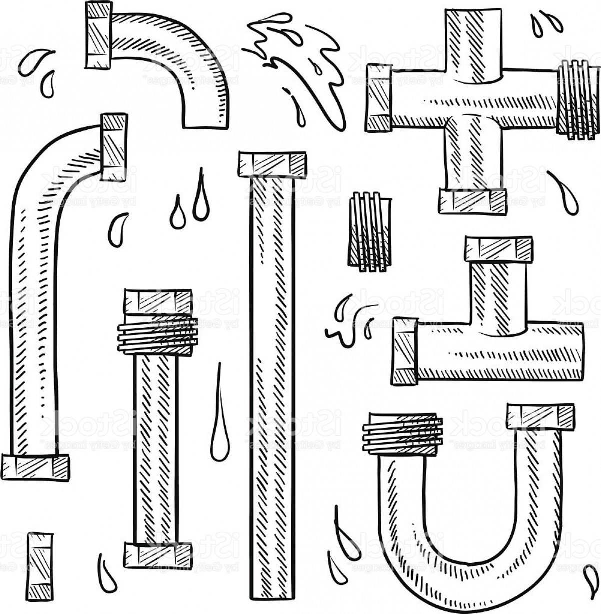
Web Piping Symbols, Also Known As Pipe Drawings, Are A Set Of Symbols Used In Metal Fabrication Drawings To Represent The Various Types Of Pipes And Fittings Used In Industrial Piping Systems.
Related Post: