Pipe Drawing
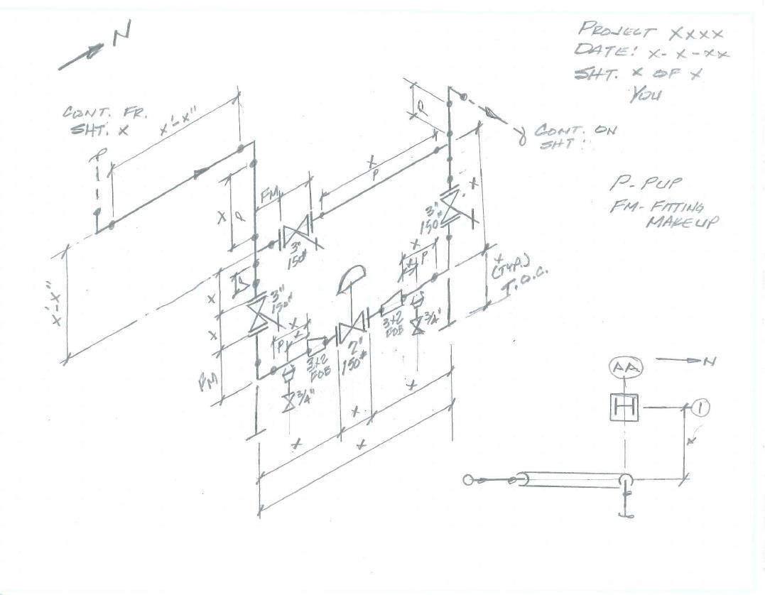
Pipe Drawing - These drawings are schematic representations and they would define functional relationships in a piping system. During operation, you have to maintain p&id in such a condition that it will show actual plant conditions at any time. Piping instrument diagram piping diagram example power plant cycle diagram. No more tedious material tracking when creating a pipe isometric drawing. Web various symbols are used to indicate piping components, instrumentation, equipments in engineering drawings such as piping and instrumentation diagram (p&id), isometric drawings, plot plan, equipment layout, welding drawings etc. How to read iso drawings. Piping isometric drawing consists of three sections. Web the main body of a piping isometric drawing is consist of: They are used for the documentation and production of complex pipework. Get tired of hand sketches and look for something better to use? No more tedious material tracking when creating a pipe isometric drawing. Web a piping and instrumentation diagram, or p&id, shows the piping and related components of a physical process flow. Available for windows, mac and linux. Web get your certificate here: Get tired of hand sketches and look for something better to use? Modern alternative to pencil and paper. The coordinate system of piping isometric. These drawings are schematic representations and they would define functional relationships in a piping system. The instructor explains the state of art in mechanical & piping. Web get your certificate here: Web the easiest way to visualize your piping process and instrumentation by using our professional piping design software. Piping instrument diagram piping diagram example power plant cycle diagram. There are usually five types of piping drawings that are prepared to communicate various information in a simple and easy way. Piping joint types, weld types. You can edit or customize any. Web a piping isometric drawing provides all the required information like: Web browse piping diagram templates and examples you can make with smartdraw. Download and install the 2025.0.1 or newer update. Any desired piping design views can be displayed on the drawing. Get tired of hand sketches and look for something better to use? Piping and component descriptions with size, quantity, and material codes. Check out these piping and instrumentation diagrams created in smartdraw. Smartdraw is used by over 85% of the fortune 500. We are concluding our first pipefitter series run with a video on how to draw isometric drawings. Web a piping system drawing may be represented by the following three methods. The clear advantage of a piping isometric drawing is its simplicity and symbolic representation of pipework, which allows it to be read quickly by all project stakeholders. This chapter is an overview of the pipe drafting and design profession. These highly structured drawings provide a comprehensive 3d representation of the arrangement, dimensions, and connections of pipes within a system. Discover the essentials of piping isometrics, including how they simplify complex piping systems for construction, maintenance, and documentation purposes. Piping isometric drawings are detailed technical illustrations that show a 3d view of piping systems. Modern alternative to pencil and paper.
How to draw a pipe real easy Step by Step with Easy, Spoken Instructions

Steel Pipe Drawing at GetDrawings Free download

How to read piping isometric drawing, Pipe fitter training, Watch the
The Drawing Sheet Sizes Shall Be Any Of The Following.
Web Posted In Design Engineering.
Web A Piping And Instrumentation Diagram, Also Called A P&Id, Is A Drawing In The Process Industry.
They Are Used For The Documentation And Production Of Complex Pipework.
Related Post: