P Id Drawing
P Id Drawing - Make your own p&id diagrams with this free online drawing tool. A diagram which shows the interconnection of process equipment and the instrumentation used to control the process. To identify components in your diagram, you can create intelligent tags. They are typically created by engineers who are designing a manufacturing process for a physical plant. You will learn how to read p&id and pefs with the help of the actual plant drawing. Dive into documentation, tutorials, videos, and troubleshooting resources. Before sketching your p&id, it's much better to make a list of all elements that you need. Web in this video, you will learn the basics of piping and instrumentation diagrams (also called p&id drawings).#pipingandinstrumentation #processcontrol #instru. Web p&id drawing is a schematic representation of instrumentations, control systems, and pipelines used in any process development plant. Web piping and instrumentation diagrams (p&ids) use specific symbols to show the connectivity of equipment, sensors, and valves in a control system. Learn the workflow of how to design a p&id drawing with plant 3d. Before sketching your p&id, it's much better to make a list of all elements that you need. P&id software built with engineers in mind. What is the end product? Discover the main international standards for p&id drawings. Web © 2024 google llc. Web visual paradigm's p&id tool features a handy diagram editor that allows you to draw p&id diagrams, industrial diagrams, and schematics quickly and easily. In the process industry, a standard set of symbols is. Are they manual or automatic? They are typically created by engineers who are designing a manufacturing process for a physical plant. All valves and their identifications. P&ids are used to develop guidelines and standards for facility operation. Discover the main international standards for p&id drawings. A link to download this p&id is given at the end of the page. Only a few steps to follow to create a p&id diagram, but one who does it should know well knowledge about the. Web visual paradigm's p&id tool features a handy diagram editor that allows you to draw p&id diagrams, industrial diagrams, and schematics quickly and easily. Mechanical equipment with names and numbers. Are they manual or automatic? Web p&id diagrams (piping and instrumentation diagrams) provide a schematic representation of the functional relationship between piping, instrumentation, and system components within a project. Discover the main international standards for p&id drawings. In the process industry, a standard set of symbols is. P&id is more complex than pfd and includes lots of details. Piping & instrumentation diagram explained. Web how to read p&id drawings. It is the basic training document to explain the process details to operation guys,. Web © 2024 google llc. Make your own p&id diagrams with this free online drawing tool. It uses symbols to represent process equipment such as sensors and controllers. A link to download this p&id is given at the end of the page. To identify components in your diagram, you can create intelligent tags. P&ids are used to develop guidelines and standards for facility operation.
P&ID Piping and Instrument Diagrams (PID) Creative Engineers, Inc.
P&ID EXAMPLE
How to Read a P&ID Drawing Quickly and Easily Edraw Max
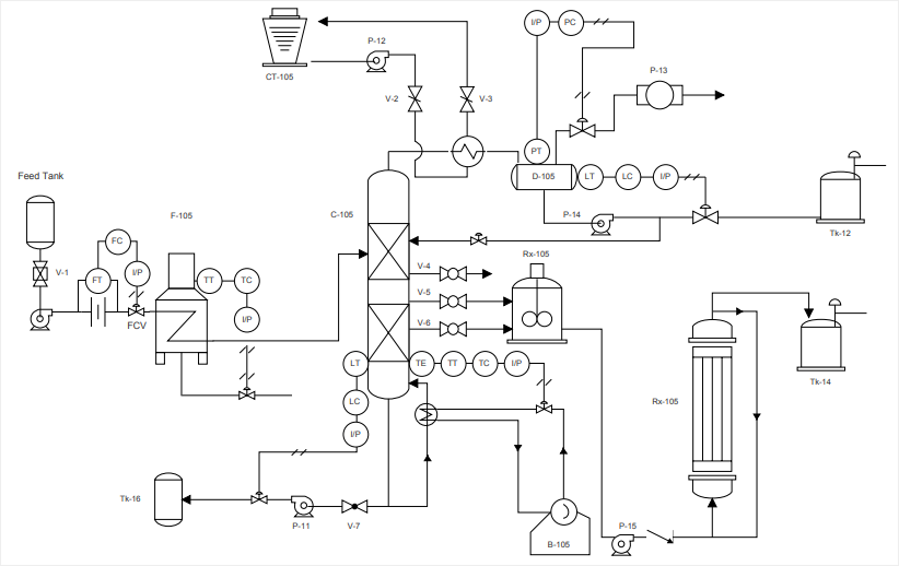
Web P&Id Drawing Is A Schematic Representation Of Instrumentations, Control Systems, And Pipelines Used In Any Process Development Plant.
These Symbols Can Represent Actuators, Sensors, And Controllers And May Be Apparent In Most, If Not All, System Diagrams.
What Is The End Product?
Web A Piping And Instrumentation Diagram (P&Id) Is Defined As Follows:
Related Post: