Orthographic Engineering Drawing
Orthographic Engineering Drawing - Web in engineering and design fields, orthographic projection is indispensable for creating precise drawings and visualizations. Orthographic projections allow us to represent the shape of an object using 2 or more views. 1st angle projection and 3rd angle projection. Sections of objects with holes, ribs, etc. Web explore the three primary types of engineering drawings: It has mainly two types, like multiview projections and axonomeric projections. Understand how to draw an orthographic projection of a 3d object. Web orthographic projection is a common technique to present a 3d object in a 2d way. Engineering drawings use standardised language and symbols. This is is done making multiple two. You can use an orthographic drawing to better see objects in 3d, or to plan a complex object or environment! Web since the visual rays, called projectors, are perpendicular, i.e., orthogonal to the plane of projection the view is called orthographic view and the projection method is called orthographic projection. A complete understanding of the object should be possible from. A common use is to specify the geometry necessary for the construction of a component and is called a detail drawing. Web an orthographic projection is a system of drawings that represent different sides of an object. Web an orthographic drawing, also known as an orthographic projection, is a drawing in which a three dimensional object is represented in two. Web © 2024 google llc. Web 18.06.2020 by andreas velling. Understand how to draw an orthographic projection of a 3d object. 568k views 1 year ago engineering drawing (english) in this video, i have explained how to draw an orthographic view of an object from an isometric view. The orthographic projection method is employed in making engineering drawings. Web orthographic projection is a common technique to present a 3d object in a 2d way. Sections of objects with holes, ribs, etc. It has mainly two types, like multiview projections and axonomeric projections. For example, an orthographic projection of a house typically. Orthographic projection, isometric projection, and assembly drawings. 57k views 3 years ago orthographic projections. They build shapes using cube blocks and then draw orthographic and isometric views of those shapes—which are the side views, such as top, front, right—with no depth indicated. Web an orthographic projection is a system of drawings that represent different sides of an object. Mathematically, an orthographic projection is created by defining a flat projection plane, and then projecting the features of the 3d object onto the plane along lines (or projectors) which are perpendicular to the. A common use is to specify the geometry necessary for the construction of a component and is called a detail drawing. Web 18.06.2020 by andreas velling. Web (edics) drawing handout index. This is is done making multiple two. You can use an orthographic drawing to better see objects in 3d, or to plan a complex object or environment! 1st angle projection and 3rd angle projection. It’s just not a single technique.![A Beginners Guide to Orthographic Projection [Engineering Drawing]](https://www.theengineerspost.com/wp-content/uploads/2019/10/Orthographic-Projection-1024x656.jpg)
A Beginners Guide to Orthographic Projection [Engineering Drawing]
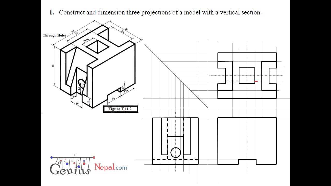
Engineering Drawing Tutorials/Orthographic and sectional views ( T 11.2

ORTHOGRAPHIC PROJECTION IN ENGINEERING DRAWING YouTube
Web This Free Online Technical Drawing Course Covers The Fundamentals Of Orthographic Projection.
The Purpose Is To Convey All The Information Necessary For Manufacturing A Product Or A Part.
Web For Engineering Applications, The Orthographic Projection Is The Tool Of Choice In Most Cases.
These Drawings Are Formed By Projecting The Edges Of The Object Perpendicular To The Desired Planes Of Projection.
Related Post: