Manufacturing Process Drawing
Manufacturing Process Drawing - These best practices apply to 2d drafting and creating technical drawings from a 3d model. Drawing is classified into two types: In this comprehensive guide, we will explore the key steps and best practices involved in creating effective assembly drawings in. Machine operators, production line workers and supervisors all use production. Manufacturing engineering drawings contain detailed component specifications. Before 3d cad software became commonplace, 2d drawings were the norm in the manufacturing industry. Engineering drawings use standardised language and symbols. • lean production, agile manufacturing Web in this article we will cover the basics of creating high quality engineering drawings for individual part designs so that you can communicate your design and manufacturing intent clearly, as well as review other drawings effectively. Deep drawing is a popular sheet metal forming method that is used in the production of a wide range of items, such as: Steps of the manufacturing process. Web drawing process is based on micropipette or glass rod application to obtain a desired structure. 9/16/2022 | 5 min read. Web engineering drawing is a specialized form of communication that uses a strict set of symbols, standards, and perspectives to depict mechanical, electrical, or structural designs. 5 applications of technical drawing in machining processes. It’s not an easy trip, but these eight steps help make it possible: Principles of design for manufacturing and assembly (dfm) assembly process design which describes how and why the assembly processes are determined. • green design, sustainable manufacturing, product life cycle. Drawing is classified into two types: Sheet metal drawing and wire, bar, and tube drawing. An engineering drawing is a subcategory of technical drawings. Web engineering drawings are used to guide the design process and manufacturing process of new products or repairs. It clearly defines the part’s design, final quality, manufacturing processes, component materials, ease of distribution, etc. Principles of design for manufacturing and assembly (dfm) assembly process design which describes how and why the. • green design, sustainable manufacturing, product life cycle. Web sheet metal drawing, a crucial manufacturing process, stands as a cornerstone in the creation of hollow, multifaceted components with a sharp focus on precision. • design for manufacturing, assembly, disassembly, service. Web what is manufacturing drawing? Web the main purpose of production drawings is to define the size, shape, location and production of the component. Machine operators, production line workers and supervisors all use production. • lean production, agile manufacturing It's most often used in chemical engineering and process engineering, though its concepts are sometimes applied to other processes as well. Web 4.1 key factors to consider while choosing between 2d and 3d. The purpose is to convey all the information necessary for manufacturing a product or a part. This is accomplished by forcing the work through a mold, (die), of smaller cross sectional area than the work. Web engineering drawing is a specialized form of communication that uses a strict set of symbols, standards, and perspectives to depict mechanical, electrical, or structural designs. Beverage cans, automotive panels, bathtubs, pots, pans, and sinks. Web incorporate devices which will allow room for inconsistencies in manufacturing and materials. Before 3d cad software became commonplace, 2d drawings were the norm in the manufacturing industry. When possible draw parts to a 1:1 scale and print to get a real sense of size.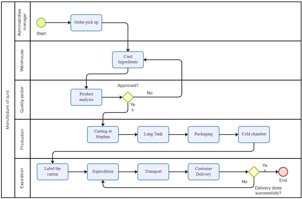
Understanding Manufacturing Process Flowcharts (With Examples)
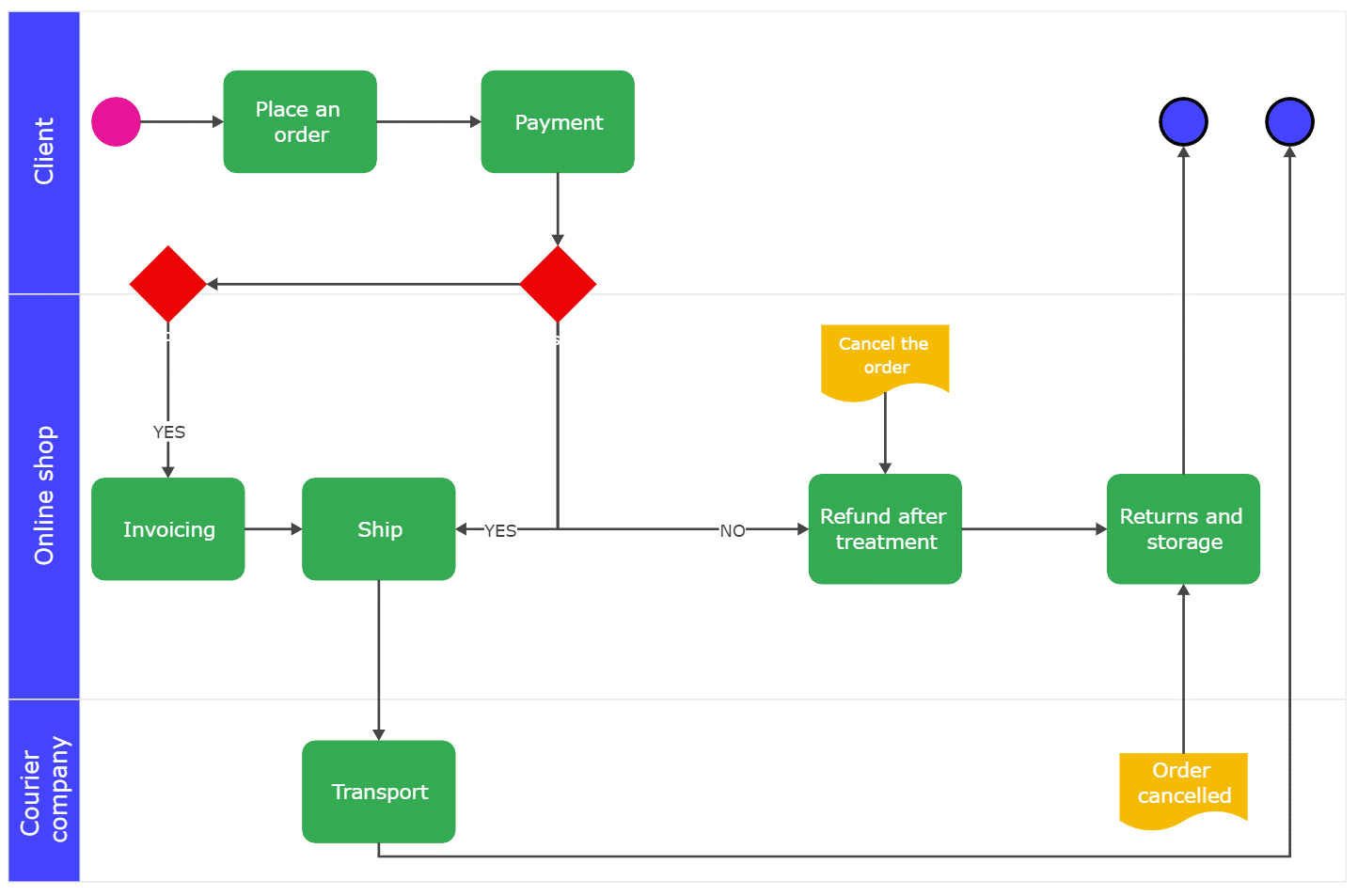
Understanding Manufacturing Process Flowcharts (With Examples)
PRODUCTION PROCESS and PROCESS PLANNING Engineers Gallery
An Engineering Drawing Is A Subcategory Of Technical Drawings.
Web Today We Will Learn About Drawing Process Working And Its Types Like Wire Drawing, Rod Drawing And Tube Drawing.
The Sharp Tip Of A Micropipette Contacts With A Polymer Solution Droplet And Subsequent Withdraw Slowly Which Leads To Producing Nanofibers.
Engineering Drawings Use Standardised Language And Symbols.
Related Post: