Loop Drawings
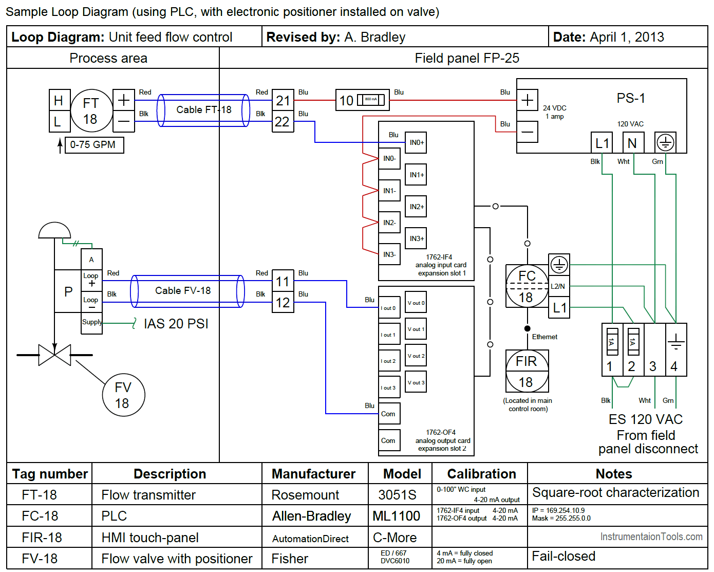
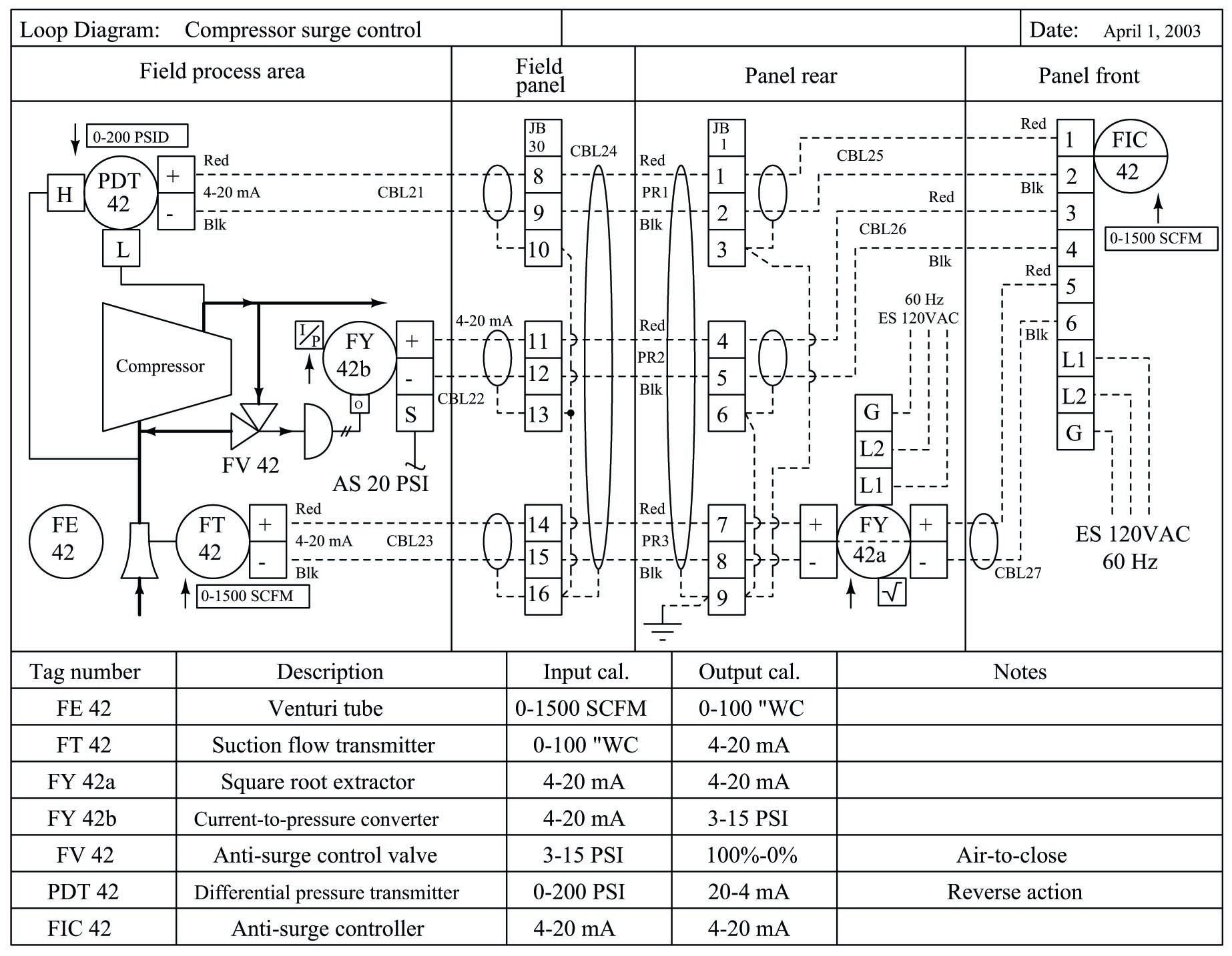
Loop Drawings - Web this video shows the basics of loop diagram.course link: Additional information for individual loop. Here we see that the p&id didn’t show us all the instruments in this control “loop.” Purpose of this particular instrumentation design deliverable is but not limited to : Updating this single diagram to as built status is more easily achieved than updating the variety of other documents. Loop diagrams are composed of wiring details of field instruments; In an automation system, ilds provide all of the necessary information concerning control loops. Web the different types of instrumentation diagrams which are commonly used are (i) process flow diagram (pfd), (ii) loop diagrams (loop sheets), (iii) process and instrument diagrams (p&id), and (iv) functional diagrams. Loop diagrams can be customized or edited as per service requirements. 1) showing how the control system is getting instruments data and how it controlling output. The ilds are also referred to as “instrument wiring diagrams.” We could easily determine where the field devices are located. These detail drawings show how each piece of equipment (e.g., instrument, motor starter, valve actuator, etc.) is to be wired to the. Web this video shows the basics of loop diagram.course link: This standard does not mandate the style and. In an automation system, ilds provide all of the necessary information concerning control loops. This standard establishes minimum required information and identifies additional optional information for a loop diagram for an individual instrumentation loop. Web this video shows the basics of loop diagram.course link: Updating this single diagram to as built status is more easily achieved than updating the variety. Basically, instrument loop diagrams represents detailed drawing showing an instrument wiring. Web this video shows the basics of loop diagram.course link: A loop diagram shows you how the instruments are arranged in the loop.from the loop diagram you can identify the connections between devices and the communication. Web what is an instrument loop diagram? Here we see that the p&id. This standard does not mandate the style and content of instrument loop diagrams, but rather it In an automation system, ilds provide all of the necessary information concerning control loops. The process is illustrated in sections or subsystems of the process called loops. Web instrument loop diagrams. Engineering costs can be reduced; Basically, instrument loop diagrams represents detailed drawing showing an instrument wiring. Web process and instrument diagrams (p&ids), also called piping and instrumentation diagrams and loop diagrams are construction and documentation drawings that show the flow of the process and illustrate the instrumentation control and measurement instructions, wiring and connections to the process. 1) showing how the control system is getting instruments data and how it controlling output. Web this video shows the basics of loop diagram.course link: Web instrument loop diagram, that information is spread among many other documents and is not readily available. This standard establishes minimum required information and identifies additional optional information for a loop diagram for an individual instrumentation loop. The ilds are also referred to as “instrument wiring diagrams.” Loop drawing from field to dcs is explained in this video. Loop drawings for smart instruments are the same as for analog loops, except for the communication links between the components (figure 1). Web instrument loop diagram represents detailed drawing showing a connection from one point to control system.loop diagram shows instrument (in a symbol) and its. A loop diagram shows you how the instruments are arranged in the loop.from the loop diagram you can identify the connections between devices and the communication.
4 wire loop drawings explained Learn Instrumentation Engineering
Instrumentation Loop Diagrams InstrumentationTools
Loop Diagrams (Loop Sheets) Control and Instrumentation Documentation
Updating This Single Diagram To As Built Status Is More Easily Achieved Than Updating The Variety Of Other Documents.
Web The Loop Diagram Is The Document Consist Of All Connections Of Instruments From The Field To The Control Panel.
The Faulty Section Can Be Easily Determined With The Help Of A Loop Diagram;
We Talk About What They Are, How Th.
Related Post: