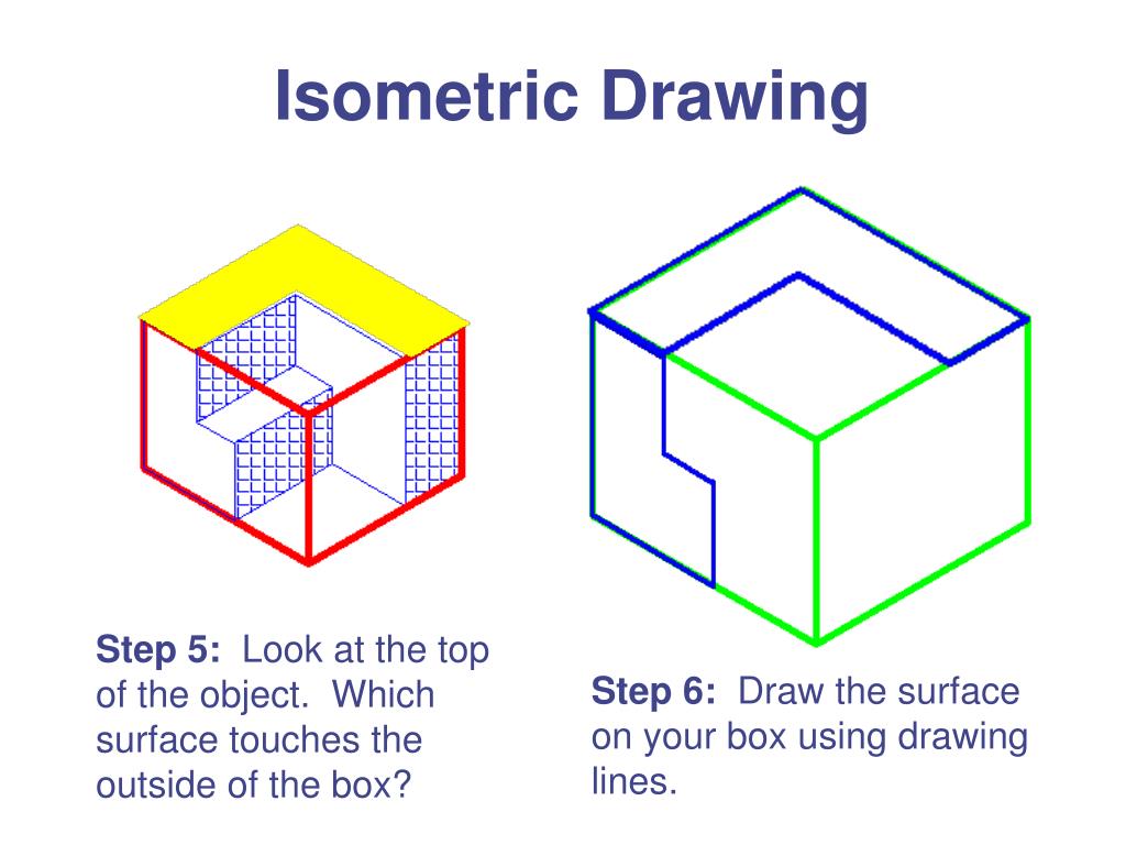
Isometric View Drawing
Isometric View Drawing - Additionally, we'll uncover the advantages of using isometric drawings and provide practical examples to illustrate their diverse applications. Draw figures using edges, faces, or cubes. The views are the top and two sides. There are three types of pictorial views: You can shift, rotate, color, decompose, and view in 2‑d or 3‑d. 28k views 7 months ago isometric view in engineering drawing. Web in an isometric drawing, the object’s vertical lines are drawn vertically, and the horizontal lines in the width and depth planes are shown at 30 degrees to the horizontal. Learn to draw isometric projections using these simple steps provided. Learn how to create stunning isometric views of objects using orthographic projections with this. Visio plan 2 visio plan 1 visio professional 2021 visio standard 2021 more. 3rd to 5th, 6th to 8th, high school. An engineering drawing is a subcategory of technical drawings. Learn to draw isometric projections using these simple steps provided. The view drawn to the exact scale is known as the isometric view (isometric drawing). And, of course, the end goal of whichever method you use is to accurately convey your design and. Learn to draw isometric projections using these simple steps provided. Draw figures using edges, faces, or cubes. While that drawn using the isometric scale is known as as the isometric projection. For this example, the block annosloperatio. The command scale can be used to. It seems to have become a 3d world out there—model this, bim that—but make no mistake, there’s still a need for old fashioned 2d drafting too. This is a good way of showing measurements and how components fit. What is an isometric drawing? For example, isometric spot icons, which tend to be larger than interface icons, can be used to. Draw figures using edges, faces, or cubes. And, of course, the end goal of whichever method you use is to accurately convey your design and creation content. This is a good way of showing measurements and how components fit. Use this interactive tool to create dynamic drawings on isometric dot paper. Web go to skew > slopesymbols > ratio. The view drawn to the exact scale is known as the isometric view (isometric drawing). The purpose is to convey all the information necessary for manufacturing a product or a part. Start by clicking on the cube along the left side; This article explains all you need to know about isometric illustrations. Open windows explorer and go to the isometric folder in your project. Engineering drawings use standardised language and symbols. The command scale can be used to. How to draw perspective and isometric drawings. While that drawn using the isometric scale is known as as the isometric projection. In this tutorial we’re going to get back to the basics and go over how to draw perspective, isometric, and 3d drawings. 195k views 1 year ago engineering drawing (english) in this video, i have explained how to draw an isometric view of an object from an orthographic.
PPT Isometric Drawing PowerPoint Presentation, free download ID3001508

What is an Isometric Drawing? Types And Step To Draw

Isometric view drawing example 1 (easy). Links to practice files in
28K Views 7 Months Ago Isometric View In Engineering Drawing.
Welcome To The 8Th Video In Our Engineering Drawing Series, Where We Simplify Isometric Drawing Using The Most.
Then, Place Cubes On The Grid Where.
The Views Are The Top And Two Sides.
Related Post: