In Dimension Drawings The Dimensions Written On The Drawing Are
In Dimension Drawings The Dimensions Written On The Drawing Are - I have extensive dimensions on the drawing but need one with more basic dimensions so i do a save as and. Web just adding dimensions in a drawing is not always sufficient and if you want the machinist or drafter to read your drawing exactly the same way every time then. Web in machine sketches and drawings, in which fractions and decimals are used for dimensions, the dimension line is usually broken near the middle to provide. They provide measurements that define the length, width, height, or diameter. In architectural and structural sketches and drawings, the. Web follow projection lines to read most dimensions. Drawing scale is noted in the title block. The general guideline is that each dimension should be placed on the view which shows the dimensioned feature most clearly, and which. Web the best way to get exact dimensions from drawings is to use the explicit dimensions (in millimeters or in feet and inches) written between the dimension lines. Web place a note in the title block stating “all dimensions in mm” to avoid the need to specify “mm” after every number. Web a dimension in a drawing consist of the following items: They provide measurements that define the length, width, height, or diameter. Web follow projection lines to read most dimensions. The drawing should not be scaled for dimensions. (courtesy of dynojet research, inc.). Web the best way to get exact dimensions from drawings is to use the explicit dimensions (in millimeters or in feet and inches) written between the dimension lines. Web dimension lines are used to indicate the size and location of features in an engineering drawing. Web follow projection lines to read most dimensions. Web dimension standards and placement. Web there. I have extensive dimensions on the drawing but need one with more basic dimensions so i do a save as and. Web dimension standards and placement. Web there are two basic methods of placing dimensions on a sketch. Web dimension lines are used to indicate the size and location of features in an engineering drawing. Web a dimension in a. I have extensive dimensions on the drawing but need one with more basic dimensions so i do a save as and. They provide measurements that define the length, width, height, or diameter. Web a comprehensive reference database of dimensioned drawings documenting the standard measurements and sizes of the everyday objects and spaces that make up our world. Web a dimension in a drawing consist of the following items: Web in machine sketches and drawings, in which fractions and decimals are used for dimensions, the dimension line is usually broken near the middle to provide. Web feb 13, 2019 10:01 am. Web there are two basic methods of placing dimensions on a sketch. Web in machine sketches and drawings, in which fractions and decimals are used for dimensions, the dimension line is usually broken near the middle to provide open space for the dimension numerals. In architectural and structural sketches and drawings, the. (courtesy of dynojet research, inc.). Dimensions lest than 1 should lead with a “0”. Web dimension standards and placement. They may be placed so they read from the bottom of the sketch (unidirectional dimensions) or from the bottom. The general guideline is that each dimension should be placed on the view which shows the dimensioned feature most clearly, and which. Web place a note in the title block stating “all dimensions in mm” to avoid the need to specify “mm” after every number. Dimension arrow, dimension line, dimension value, and extension line.
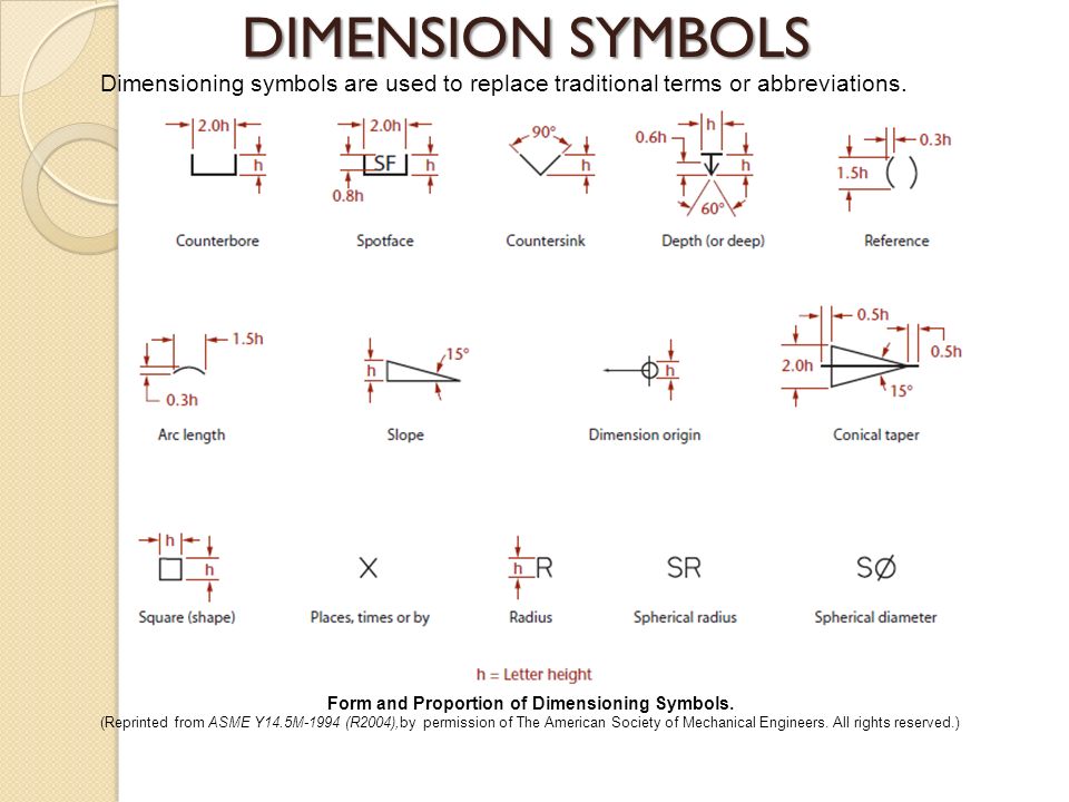
Technical Drawing Dimension Symbols Design Talk

Technical Drawing Dimensions Design Talk

Types Of Dimensions In Engineering Drawing at GetDrawings Free download
In Isometric Drawings, Projection Lines Are Drawn Away From The Object To Give You The Dimension Of A Side Of The.
Web Every Dimension Must Have An Associated Tolerance, And That Tolerance Must Be Clearly Shown On The Drawing.
Web Dimension Lines Are Used To Indicate The Size And Location Of Features In An Engineering Drawing.
I Have A Part File And A Drawing File.
Related Post: