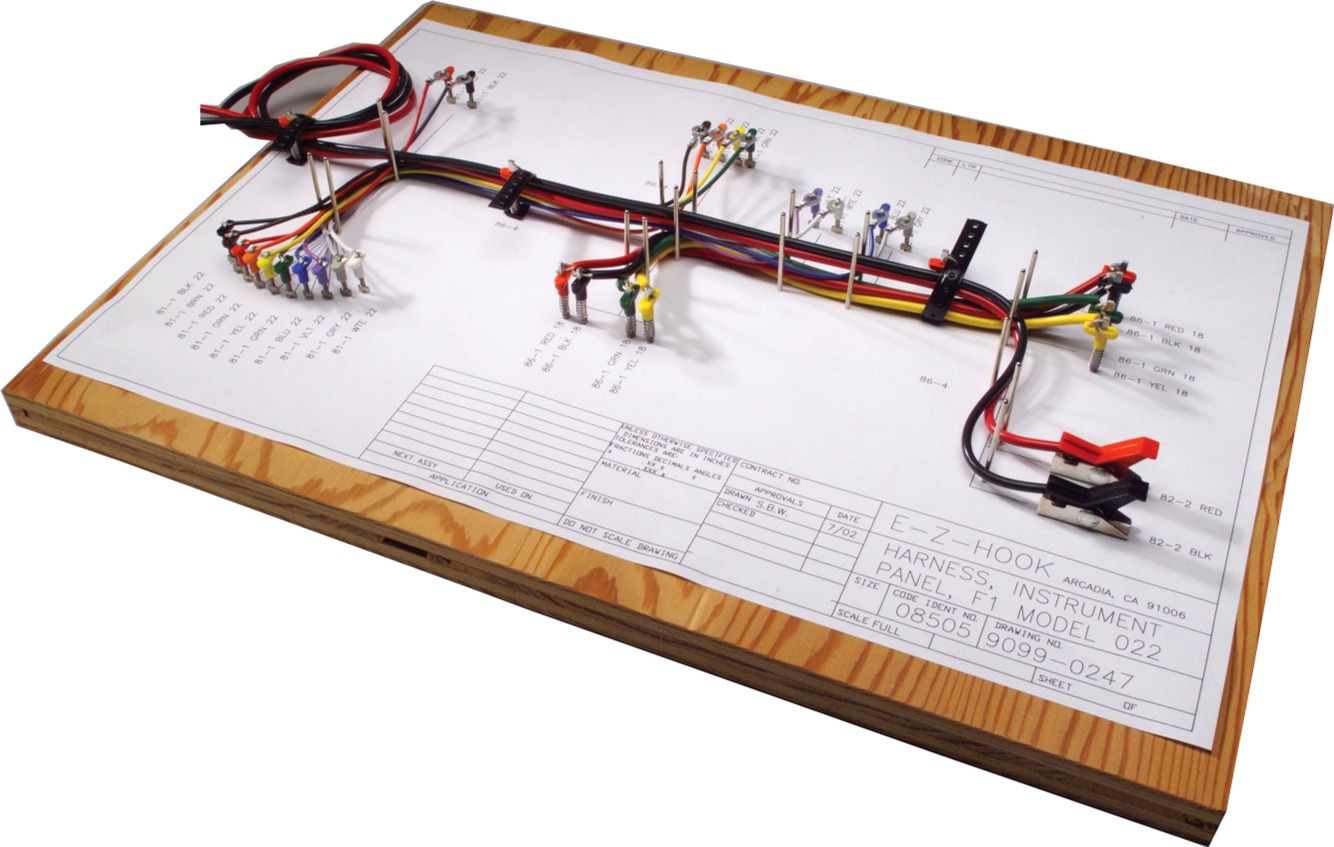
Harness Drawing
Harness Drawing - Doing the cable assembly drawing in a printed board layout assembly. A wire harness diagram, also known as a wiring diagram or electrical schematic, is a visual representation of the electrical connections and functions of a wire harness. Sainesh solanki continues his blog series on using schematic cad tools for cable and wiring harness design. Draw a physical layout on a 1:1 drawing and plan on plotting it full size. November 03, 2023 | updated: The capabilities of nx cad wire harness routing enable you to produce a wire harness directly from nx product assembly models. January 17, 2024 | applies to version: Once the harness design has been captured in the form of a wiring diagram, the physical representation of the design can be created as a harness layout drawing ( *.ldrdoc ). The features available depend on your level of altium designer software subscription. Contains a top level view (optionally as a 1:1 formboard), bill of materials, wiring table, cutlist, and other associated documents. Any slight mistake here can greatly affect the production and effectiveness of the final product. Web begin with the exact wiring diagram template you need for your house or office—not just a blank screen. March 19, 2024 | applies to version: Web a manufacturing drawing document allows a bill of materials (bom), wiring list, connection table, and a generic table. November 30, 2023 | updated: Sainesh solanki continues his blog series on using schematic cad tools for cable and wiring harness design. Web a wiring harness diagram is a visual representation of the electrical wiring system in a vehicle or any other electrical device. Whether you’re working on quick test articles or aerospace grade drawings, rapidharness will revolutionize the way. Web defining the wiring diagram. Web by allie / march 29, 2022. Web a manufacturing drawing document allows a bill of materials (bom), wiring list, connection table, and a generic table to be placed on the drawing. Once the harness design has been captured in the form of a wiring diagram, the physical representation of the design can be created. March 19, 2024 | applies to version: Web quickly draw & document harnesses. November 30, 2023 | updated: The features available depend on your level of altium designer software subscription. Transform the way you design, manufacture and collaborate. Connectors and their associated parts. Complete schematic of a wire harness diagram. Once the harness design has been captured in the form of a wiring diagram, the physical representation of the design can be created as a harness layout drawing ( *.ldrdoc ). The tabular data is directly derived from the project files and provides a simple, visual way to convey crucial information for the harness manufacturing processes. The designing and drawing of a wiring harness are the basics of the entire process. Web by allie / march 29, 2022. Used to model electrical schematics connecting one or more harnesses and devices. L3 cable/harness drawings have evolved over time to meet the needs and requirements of l3 programs. Associated parts of connection points. November 03, 2023 | updated: Web they are used to draw a complete schematic of a wire harness diagram.
How to use Schematic CAD for Harness Drawings and Cable Assemblies

Creating Cable Harness Drawings with SOLIDWORKS Electrical 3D

How To Read Wiring Harness Drawing Wiring Draw And Schematic
The Individual Wired Connections Within The Harness Are Specified In The Harness Wiring.
Web Quickly Document A Complete Harness From Drawings Or Wire List.
First, Understand What A Wire Harness Is, Then We’ll Discuss The Steps Involved In Designing A Wire Harness.
Web A Manufacturing Drawing Document Allows A Bill Of Materials (Bom), Wiring List, Connection Table, And A Generic Table To Be Placed On The Drawing.
Related Post: