Fillet Symbol In Engineering Drawing
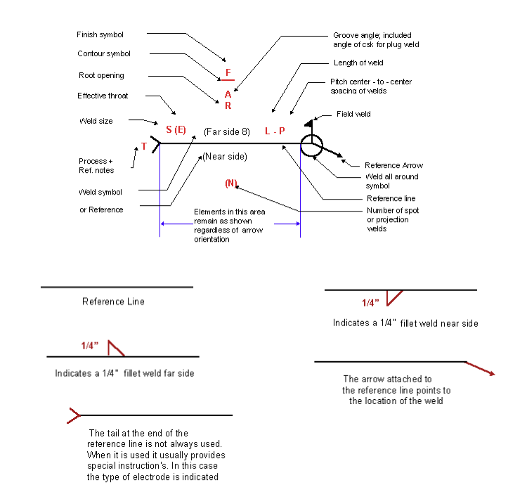
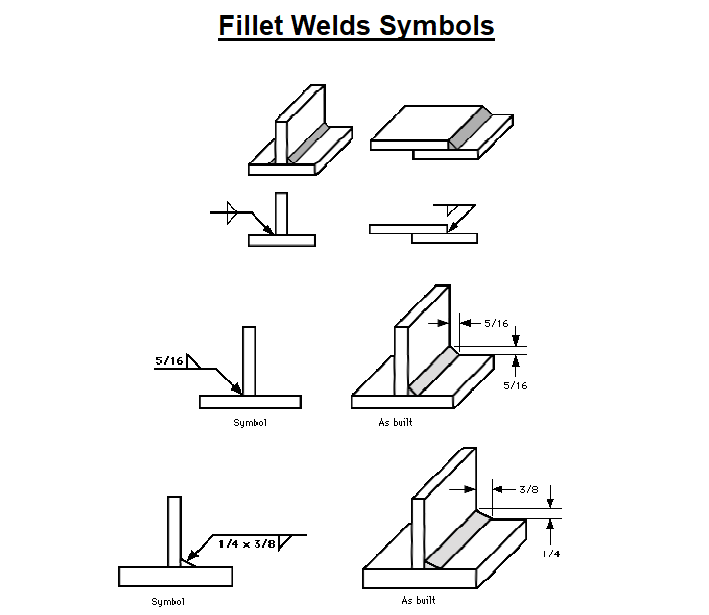
Fillet Symbol In Engineering Drawing - Different types of basic weld symbols make up the fabrication or engineering drawings. Web the fillet weld symbol is a right triangle placed on the reference line with the perpendicular leg always on the left. Engineering drawing symbols play a vital role in communication among engineers and other stakeholders involved in the design and construction process. Web drawing of weld symbols. These welds can be applied on varying angles but this would be the most prominent. • grooved—square, bevel, v, u, and j. Web engineering drawing abbreviations and symbols are used to communicate and detail the characteristics of an engineering drawing. You are more than likely going to come across welds on engineering and fabrication drawings. These are a set of symbols that describe the weld, the weld leg size, as well as giving processing and finishing information. The british standard for weld symbols was bs en 22553 which has been superseded by bs en iso 2553:2019. The weld symbol always includes. Engineering drawing symbols play a vital role in communication among engineers and other stakeholders involved in the design and construction process. For the sake of graphical clarity, the drawings below do not show the penetration of the weld metal. This list includes abbreviations common to the vocabulary of people who work with engineering drawings in. Web the most important symbols that you do have to memorize are the fillet weld symbol and the groove weld symbol. The radius value is given next to the symbol. Fillet welds are one of the most common weld types in the industry. Web welding symbols and drawings are essential for learning and understanding the correct way of welding. You. These welds can be applied on varying angles but this would be the most prominent. In the case of fillet welding, the drawings and symbols and their correct interpretations are critical to learning the basics of fillet welding. Web fillet weld symbols explained. Web fillet welding is a technique used to join two metal pieces together by welding at an. The british standard for weld symbols was bs en 22553 which has been superseded by bs en iso 2553:2019. Web a fillet weld symbol can be used with an arrow side (below reference line) other side (above reference line) significance or on both sides (both sides of the reference line.) when a fillet weld is required on both sides. Engineering drawing symbols play a vital role in communication among engineers and other stakeholders involved in the design and construction process. Web we notice welding symbols in fabrication & engineering drawings where lines and special geometrical shapes such as triangles, circles, etc. Different types of basic weld symbols make up the fabrication or engineering drawings. Are used to give details about the weld type, weld size, & other supportive information such as welding process, surface finish requirements, etc. Web drawing of weld symbols. Web basic weld symbols. The radius value is given next to the symbol. Web the examples of the weld all around and field weld above show a fillet weld symbol so that the weld to be applied in both cases is a fillet weld. This list includes abbreviations common to the vocabulary of people who work with engineering drawings in the manufacture and inspection of parts and assemblies. Fillet welds are one of the most common weld types in the industry. Web in engineering drawings, fillets and rounds are typically specified using dimensional tolerances and geometrical tolerance symbols. This weld is used when the joint has two members coming together to form an intersection of commonly 90 degrees. Fillet welds are one of the most common weld types in the industry. Web fillet welding is a technique used to join two metal pieces together by welding at an approximately right angle.![[SOLVED] In engineering drawing, the welding symbol used for fillet](https://storage.googleapis.com/tb-img/production/20/08/weld symbol1.PNG)
[SOLVED] In engineering drawing, the welding symbol used for fillet
Understanding the Welding Symbols in Engineering Drawings Safe Work
Understanding the Welding Symbols in Engineering Drawings Safe Work
Gb/T 5185 Designation Of Metal Welding And Brazing Methods In Drawings;
Fillet Welds Are Some Of The Most Common Welds You’ll Encounter As A Welder.
Web For Fillet Welds, Numbers To The Left Of The Symbol Indicate The Design Throat Thickness, Leg Length (Leg Size), Or Both Design Throat Thickness And Leg Length Requirements.
The Aws Defines A Fillet Weld As:
Related Post: