Engineering Drawing Symbols
Engineering Drawing Symbols - Mastering these standards will give. Asme y14.5.1 2019 mathematical definition of dimensioning and tolerancing principles standard. We will treat “sketching” and “drawing” as one. The following is a short list of symbols that normally appear on a technical drawing and need understanding. The mechanical engineering branch, mechanical systems division, has been delegated Geometric tolerances are specified using symbols on a drawing. Here are more commonly used engineering drawing symbols and design elements as below. Web how to read an engineering drawing symbol. An engineering (or technical) drawing is a graphical representation of a part, assembly, system, or structure and it can be produced using freehand, mechanical tools, or computer methods. This is the place to learn about engineering symbology, different types of drawings and documents, and how to use modern technology to simplify collaboration. It includes a set of symbols, text, and tolerances that provide precise information about the size, shape, and orientation of parts and assemblies. This is the place to learn about engineering symbology, different types of drawings and documents, and how to use modern technology to simplify collaboration. Why not just use a 3d model? Web welcome to our engineering drawing. Unlike a model, engineering drawings offer more specific detail and requirements, such as: We offer you our tips which we believe are useful for dispelling uncertainty by comparing the symbol with its graphic representation. Currently, we have 16 symbols for geometric tolerances, which are categorized according to the tolerance they specify. It is more than simply a drawing, it is. For example, cold rolled steel is often abbreviated as crs, and diameter is often abbreviated as dia, d, or ⌀. There are literally hundreds of engineering drawing symbols and they’re used in a variety of ways. Web asme y14.5 2018 dimensioning and tolerancing standard. Web it establishes symbols, rules, definitions, requirements, defaults, and recommended practices for stating and interpreting gd&t. An introduction to the different types of blueprint tolerances you will encounter with plenty of examples to make them easy to understand. Web this chapter will introduce the five common categories of drawings. Web how to read an engineering drawing symbol. Web welcome to our engineering drawing symbols hub. Web gd&t symbols charts for engineering drawing & drafting | geotol. Why not just use a 3d model? Any needed height h 2 h h 2 h 60° 2 h identification letter datum feature symbol datum target symbol target point and. Why abbreviations and symbols are needed for engineering drawing? Web engineering drawings (aka blueprints, prints, drawings, mechanical drawings) are a rich and specific outline that shows all the information and requirements needed to manufacture an item or product. Web gd&t drawings and symbols. The following tables show how to construct the symbols. Mastering these standards will give. Web the gsfc engineering drawing standards manual is the official source for the requirements and interpretations to be used in the development and presentation of engineering drawings and related documentation for the gsfc. Establishes symbols, rules, definitions, requirements, defaults, and recommended practices for stating and interpreting geometric dimensioning & tolerancing (gd&t). For example, cold rolled steel is often abbreviated as crs, and diameter is often abbreviated as dia, d, or ⌀. Views, dimensions, tolerances, symbols, datum’s, feature control frames & title blocks.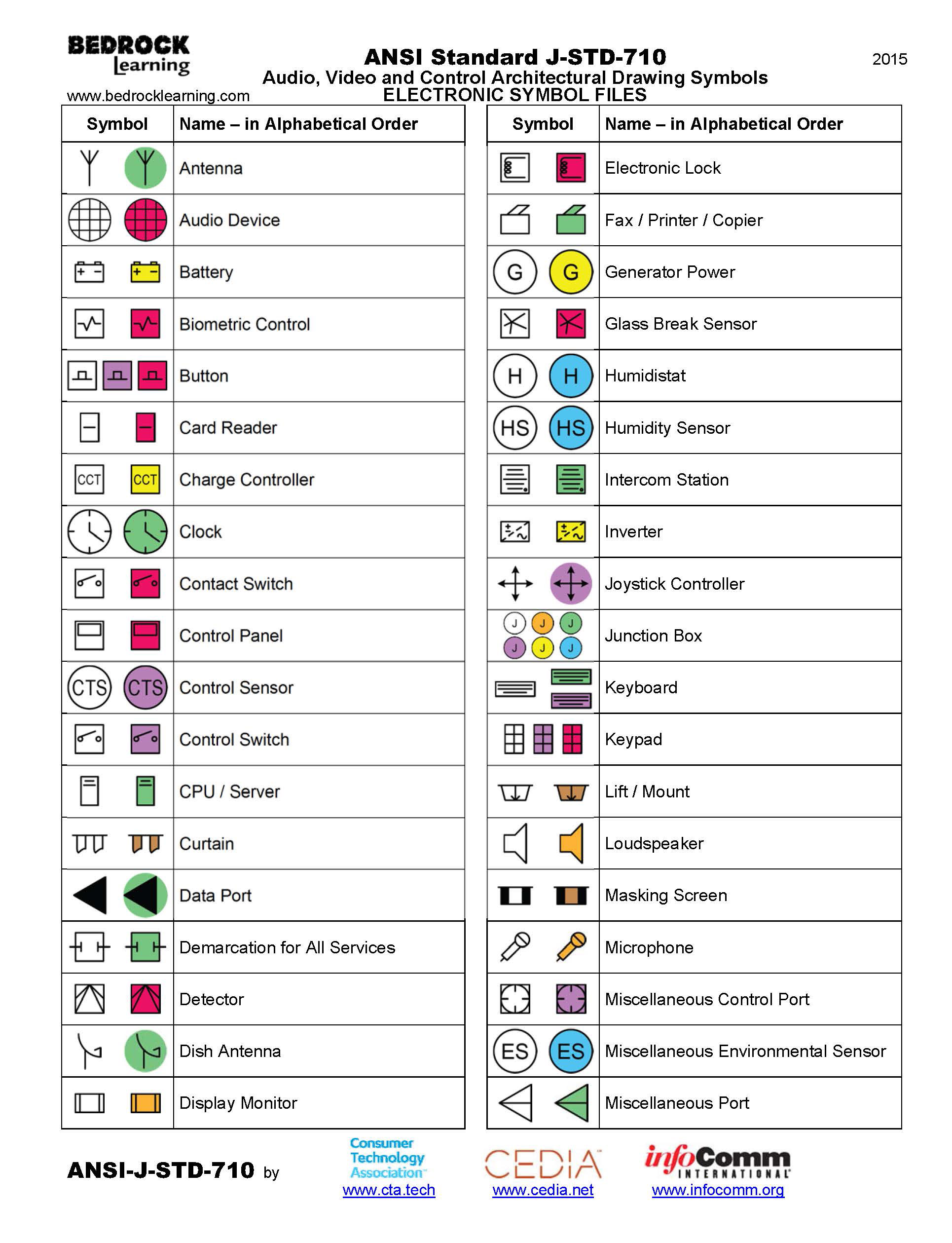
Architectural Drawing Symbols Free Download at GetDrawings Free download

Engineering Drawing Symbols And Their Meanings Pdf at PaintingValley
M&e Drawing Symbols Back To Basics Komseq
Web Engineering Drawings Use Standardised Language And Symbols.
Geometric Tolerances Are Specified Using Symbols On A Drawing.
It Is More Than Simply A Drawing, It Is A Graphical Language That Communicates Ideas And Information.
Need To Know For Dispelling Uncertainty In Drawings.
Related Post:
