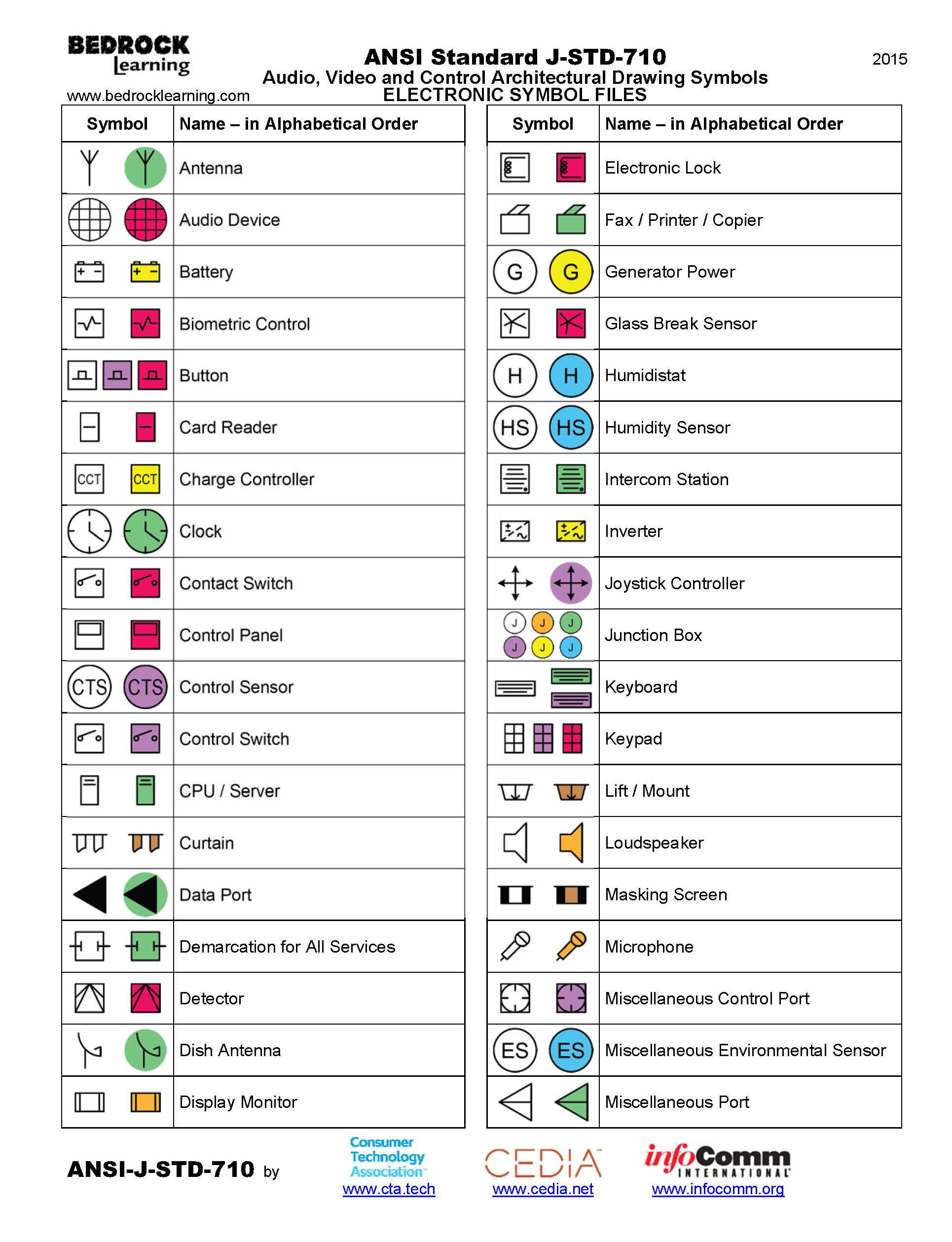
Engineering Drawing Notation
Engineering Drawing Notation - It describes typical applications and minimum content requirements. Web this page explains the 16 symbols used in gd&t, and the classification thereof. One of the best ways to communicate one’s ideas is through some form of picture or drawing. Drawings for specialized engineering disciplines (e.g., marine, civil, construction, optics, etc.) are not included in this. Web the technical engineering drawing abbreviations we outline here are the terms used in the manufacturing and inspection of parts and assemblies. We will treat “sketching” and “drawing” as one. Our guide to holes of all types and the most common blueprint callouts associated with them. Web gd&t symbols charts for engineering drawing & drafting | geotol. Despite advances, 2d mechanical drawings are still the most popular format for design documentation. This is especially true for the engineer. The table shows dimensioning symbols found on drawings. Web this page explains the 16 symbols used in gd&t, and the classification thereof. To limit errors caused by personal interpretation, engineering drawings and diagrams are governed by standardized language and symbols. Web various symbols and abbreviations in engineering drawings give you information about the dimensions, design, and materials used. Web it. “sketching” generally means freehand drawing. Web an engineering drawing is a subcategory of technical drawings. To read and understand engineering fluid diagrams and prints, usually referred to as p&ids, an individual must be familiar with the basic symbols. Web a convenient guide for geometric dimensioning and tolerancing (gd&t) symbols at your fingertips. Despite advances, 2d mechanical drawings are still the. Engineering drawings use standardised language and symbols. Click on the links below to learn more about each gd&t symbol or concept, and be sure to download the free wall chart for a quick reference when at your desk or. This manual sets forth the minimum requirements acceptable at gsfc for the preparation of engineering drawings for flight hardware and ground. This is a complete guide to the types of holes found in machining. Click here for more about holes. They are 1) piping and instrument drawings (p&ids), 2) electrical single lines and schematics, 3) electronic diagrams and schematics, 4) logic diagrams and prints, and 5) fabrication, construction, and architectural drawings. Engineering graphics is used in the design process for visualization, communication, and documentation. Web this chapter will introduce the five common categories of drawings. Web engineering drawings (aka blueprints, prints, drawings, mechanical drawings) are a rich and specific outline that shows all the information and requirements needed to manufacture an item or product. Our guide to holes of all types and the most common blueprint callouts associated with them. This standard defines the types of engineering drawings most frequently used to establish engineering requirements. The symbols used for each hole and how they are shown on engineering drawings. To read and understand engineering fluid diagrams and prints, usually referred to as p&ids, an individual must be familiar with the basic symbols. It is more than simply a drawing, it is a graphical language that communicates ideas and information. How each type of hole is used in engineering. Web the technical engineering drawing abbreviations we outline here are the terms used in the manufacturing and inspection of parts and assemblies. Web engineering and drafting personnel in the preparation, revision, and completion of engineering drawings. “learning gd&t from scratch,” provided by keyence, walks you through the basics of geometric dimensioning and tolerancing, datums, and measurements by coordinate measuring. Usually, a number of drawings are necessary to completely specify even a simple component.
Mechanical Engineering Drawing Symbols Pdf Free Download at

Engineering Drawing Symbols And Their Meanings Pdf at PaintingValley

ANSI Standard JSTD710 Architectural Drawing Symbols Bedrock Learning
Web This Page Explains The 16 Symbols Used In Gd&T, And The Classification Thereof.
Web Engineering Working Drawings Basics.
Web Gd&T Symbols Charts For Engineering Drawing & Drafting | Geotol.
The Different Types Of Holes Used In Machining.
Related Post: