Engineering Drawing Means
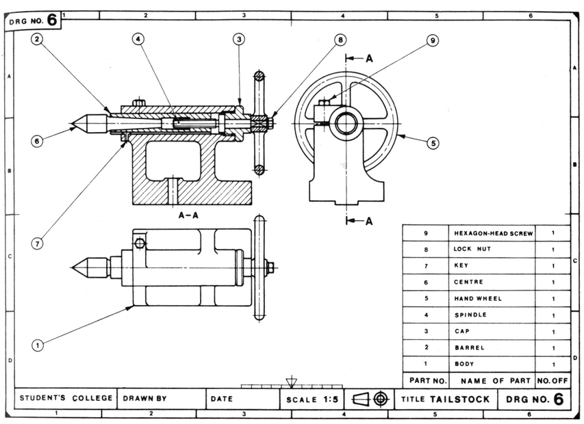
Engineering Drawing Means - Web engineering drawings (aka blueprints, prints, drawings, mechanical drawings) are a rich and specific outline that shows all the information and requirements needed to manufacture an item or product. In general, it provides necessary information about the shape, size, surface quality, material, manufacturing process, etc. Web engineering drawing abbreviations and symbols are used to communicate and detail the characteristics of an engineering drawing. In graphics communication practice there is the whole collection of different lines, which are used for drawing purposes. This list includes abbreviations common to the vocabulary of people who work with engineering drawings in the manufacture and inspection of parts and assemblies. This standard defines the types of engineering drawings most frequently used to establish engineering requirements. Hence the art of reading and creating the drawing is fundamental knowledge for any mechanical engineer. What is the main image, which we are using in all our projects, designs, drawings? Web just as an architectural drawing or blueprint shows you how to construct a building, an engineering drawing shows you how to manufacture a specific item or product. 1.2 historical background and evolution. The different types of holes used in machining. Web an engineering drawing is a type of technical drawing that is used to convey information about an object. 1.3 importance in various fields like mechanical engineering, civil engineering, etc. Web an engineering drawing is a type of technical drawing used to define the requirements for engineering products or components. Usually, a. Engineering drawing is a specialized form of technical drawing used to communicate detailed design and construction information, including dimensions, tolerances, and specifications. Engineering drawings use standardised language and symbols. 1.4 types of engineering drawing: What the difference is between counterbore and countersink holes. Web the technical engineering drawing abbreviations we outline here are the terms used in the manufacturing and. Why not just use a 3d model? It is more than simply a drawing, it is a graphical language that communicates ideas and information. Various symbols and abbreviations in engineering drawings give you information about the dimensions, design, and materials used. What is the main image, which we are using in all our projects, designs, drawings? 1.3 importance in various. Web just as an architectural drawing or blueprint shows you how to construct a building, an engineering drawing shows you how to manufacture a specific item or product. How each type of hole is used in engineering. What the difference is between counterbore and countersink holes. Web an engineering drawing is a subcategory of technical drawings that show the shape, structure, dimensions, tolerances, accuracy and other requirements needed to manufacture a product or part. 1.1 definition and overview of engineering drawing. This standard defines the types of engineering drawings most frequently used to establish engineering requirements. This list includes abbreviations common to the vocabulary of people who work with engineering drawings in the manufacture and inspection of parts and assemblies. The different types of holes used in machining. Web the technical engineering drawing abbreviations we outline here are the terms used in the manufacturing and inspection of parts and assemblies. Web engineering drawings (aka blueprints, prints, drawings, mechanical drawings) are a rich and specific outline that shows all the information and requirements needed to manufacture an item or product. Engineering drawing is a specialized form of technical drawing used to communicate detailed design and construction information, including dimensions, tolerances, and specifications. Web the purpose of this guide is to give you the basics of engineering sketching and drawing. You can think about engineering drawing as a fundamental piece of information in mechanical engineering; We will treat “sketching” and “drawing” as one. In general, it provides necessary information about the shape, size, surface quality, material, manufacturing process, etc. This is a complete guide to the types of holes found in machining.
Collection of some important material (Tutorial, Solution, Old Question
Lecture Notes Engineering Drawing Part 5
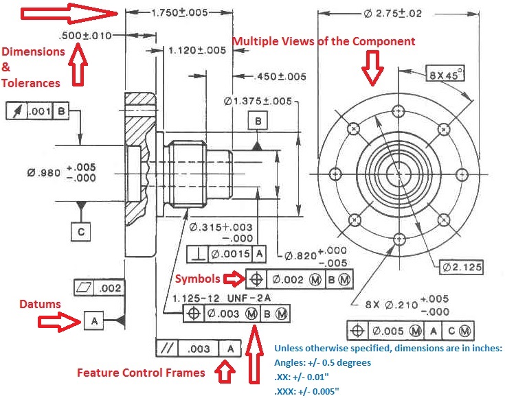
Engineering Drawings & GD&T For the Quality Engineer
Web Engineering Drawings Are The Industry's Means Of Communicating Detailed And Accurate Information On How To Fabricate, Assemble, Troubleshoot, Repair, And Operate A Piece Of Equipment Or A System.
The Rules For Creating Engineering Drawings (Communication) Are Defined By A Standards Organization (For Example, Iso And Asme ).
Web An Engineering Drawing Is A Type Of Technical Drawing That Is Used To Convey Information About An Object.
This List Includes Abbreviations Common To The Vocabulary Of People Who Work With Engineering Drawings In The Manufacture And Inspection Of Parts And Assemblies.
Related Post: