Engineering Drawing Meaning
Engineering Drawing Meaning - The video below covers the fundamentals, including the different types of views, first and third angle projection methods, dimensioning, tolerancing, best practices when creating drawings. Here we collected the standard engineering drawing abbreviations and symbols to provide help for users. The symbols used for each hole and how they are shown on engineering drawings. Web engineering drawings are key tools that engineers use to communicate, but deciphering them isn’t always straightforward. Web engineering drawing is a specialized form of communication that uses a strict set of symbols, standards, and perspectives to depict mechanical, electrical, or structural designs. The different types of holes used in machining. What the difference is between counterbore and countersink holes. How each type of hole is used in engineering. Click on the links below to learn more about each gd&t symbol or concept, and be sure to download the free wall chart for a quick reference when at your desk or on the shop floor. Dimension elements dimensioning a drawing also identifies the tolerance (or accuracy) required for each dimension. It is more than simply a drawing, it is a graphical language that communicates ideas and information. Engineering drawings use standardised language and symbols. We will treat “sketching” and “drawing” as one. The symbols used for each hole and how they are shown on engineering drawings. Web these abbreviations used in engineering drawings along with symbols to specify the details. Web the purpose of this guide is to give you the basics of engineering sketching and drawing. Web gd&t symbols | gd&t basics. We will treat “sketching” and “drawing” as one. Web dimensioning practice once the shape of a part is defined with an orthographic drawing (i.e., in projections), the size information is added in the form of dimensions. Web. This standard defines the types of engineering drawings most frequently used to establish engineering requirements. Web engineering drawings are the industry's means of communicating detailed and accurate information on how to fabricate, assemble, troubleshoot, repair, and operate a piece of equipment or a system. You can think about engineering drawing as a fundamental piece of information in mechanical engineering; An. An engineering (or technical) drawing is a graphical representation of a part, assembly, system, or structure and it can be produced using freehand, mechanical tools, or computer methods. Web engineering drawings, also known as mechanical drawings, manufacturing blueprints, drawings, etc., are technical drawings that show the shape, structure, dimensions, tolerances, accuracy, and other requirements of a part in the form of a plan. Web just as an architectural drawing or blueprint shows you how to construct a building, an engineering drawing shows you how to manufacture a specific item or product. This makes understanding the drawings simple with little to no personal interpretation possibilities. 1.2 historical background and evolution. 1.3 importance in various fields like mechanical engineering, civil engineering, etc. The purpose is to convey all the information necessary for manufacturing a product or a part. The video below covers the fundamentals, including the different types of views, first and third angle projection methods, dimensioning, tolerancing, best practices when creating drawings. This list includes abbreviations common to the vocabulary of people who work with engineering drawings in the manufacture and inspection of parts and assemblies. The engineering drawings prepared by gsfc design personnel or contractors on gsfc Web engineering drawing symbols play a vital role in communication among engineers and other stakeholders involved in the design and construction process. What the difference is between counterbore and countersink holes. Hence the art of reading and creating the drawing is fundamental knowledge for any mechanical engineer. Engineering drawings use standardised language and symbols. It helps to define the requirements of an engineering part and conveys. You can think about engineering drawing as a fundamental piece of information in mechanical engineering;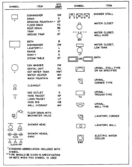
Civil Engineering Drawing Symbols And Their Meanings at PaintingValley
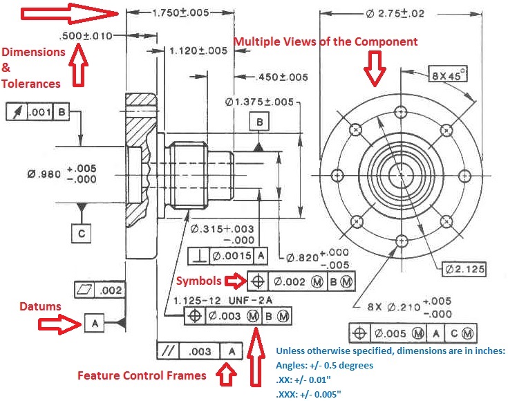
Engineering Drawings & GD&T For the Quality Engineer

Engineering Drawing Symbols And Their Meanings Pdf at PaintingValley
“Sketching” Generally Means Freehand Drawing.
1.4 Types Of Engineering Drawing:
In This Guide You’ll Learn:
Web Every Phase Of Engineering Design Starting From Concept Illustration All The Way To The Manufacturing Phase.
Related Post: