Engineering Drawing Key
Engineering Drawing Key - Web to see an animated version of this tutorial, please see the drawing and drafting section in mit’s engineering design instructional computer system. They are 1) piping and instrument drawings (p&ids), 2) electrical single lines and schematics, 3) electronic diagrams and schematics, 4) logic diagrams and prints, and 5) fabrication, construction, and architectural drawings. Web the technical engineering drawing abbreviations we outline here are the terms used in the manufacturing and inspection of parts and assemblies. Now we will dig deeper into the basic elements of engineering drawings and explain each of them in more detail. The video below covers the fundamentals, including the different types of views, first and third angle projection methods, dimensioning, tolerancing, best practices when creating drawings. Web here are some key pieces of engineering drawing infrastructure that you can create to help your team be more efficient, include complete information, and prevent repeated mistakes. Furthermore, we showed you how the usual detailed and assembly drawing looks like. Web engineering drawings (aka blueprints, prints, drawings, mechanical drawings) are a rich and specific outline that shows all the information and requirements needed to manufacture an item or product. Key elements of an engineering drawing. Engineering drawings fundamentals introduces the fundamental concepts that are required to read, understand, and interpret engineering drawings used throughout the manufacturing industry. Set up drawing sheet templates in your cad software with appropriate default tolerances, references to standards, and alphanumeric grid lines. An engineering drawing is a subcategory of technical drawings. Representative or member of a corporation, educational institution, or trade. Web engineering drawings fundamentals course. Web to see an animated version of this tutorial, please see the drawing and drafting section. Common components of engineering drawings. Methods of making engineering drawing. Web engineering drawing basics. Engineering graphics is used in the design process for visualization, communication, and documentation. Web the technical engineering drawing abbreviations we outline here are the terms used in the manufacturing and inspection of parts and assemblies. 4.2 tips for sketching, dimensioning, and detailing. Engineering graphics is used in the design process for visualization, communication, and documentation. Web the rules for creating engineering drawings (communication) are defined by a standards organization (for example, iso and asme). Web the technical engineering drawing abbreviations we outline here are the terms used in the manufacturing and inspection of parts and. Set up drawing sheet templates in your cad software with appropriate default tolerances, references to standards, and alphanumeric grid lines. A key is a piece of mild steel inserted between the shaft and hub or boss of the pulley to connect these together in order to prevent relative motion between them. Methods of making engineering drawing. An engineering drawing is a subcategory of technical drawings. Web engineering working drawings basics. Web what will we learn? Engineering graphics is used in the design process for visualization, communication, and documentation. Keys are used as temporary fastenings and are subjected to considerable crushing and shearing stresses. Common components of engineering drawings. The video below covers the fundamentals, including the different types of views, first and third angle projection methods, dimensioning, tolerancing, best practices when creating drawings. Web engineering drawings are key tools that engineers use to communicate, but deciphering them isn’t always straightforward. It is more than simply a drawing, it is a graphical language that communicates ideas and information. Now we will dig deeper into the basic elements of engineering drawings and explain each of them in more detail. The purpose is to convey all the information necessary for manufacturing a product or a part. Web what are some key tips for improving my engineering drawings? Engineering drawings use standardised language and symbols.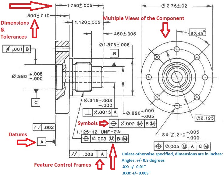
Engineering Drawings & GD&T For the Quality Engineer

Engineering Drawing Symbols And Their Meanings Pdf at PaintingValley

How To Read Architectural Drawings Symbols The Architect
Web Engineering Drawings (Aka Blueprints, Prints, Drawings, Mechanical Drawings) Are A Rich And Specific Outline That Shows All The Information And Requirements Needed To Manufacture An Item Or Product.
Key Elements Of An Engineering Drawing.
Web Engineering Drawings, Also Known As Mechanical Drawings, Manufacturing Blueprints, Drawings, Etc., Are Technical Drawings That Show The Shape, Structure, Dimensions, Tolerances, Accuracy, And Other Requirements Of A Part In The Form Of A Plan.
Web To See An Animated Version Of This Tutorial, Please See The Drawing And Drafting Section In Mit’s Engineering Design Instructional Computer System.
Related Post: