Engineering Drawing Information Box
Engineering Drawing Information Box - Drawings have an information box or title block containing who drew the drawing, who approved it, units of dimensions, meaning of views, the title of the drawing and the drawing number. Web according to iso 29845:2011, drawing is “technical information, given on an information carrier, graphically presented in accordance with agreed rules and usually to scale.” although engineers created the engineering drawings in the past by hand, today, they are primarily done in cad software like autodesk fusion 360. The name of the company or organization. It is more than simply a drawing, it is a graphical language that communicates ideas and information. Engineering drawings use standardised language and symbols. These drawings are essentially the blueprints or plans for manufacturing a wide array of products and structures. Web an engineering drawing is a visual representation that communicates the design, dimensions, and specifications of an object or assembly. An isometric drawing allows you to sketch the depth of an object. Web engineering drawings are a collection of standardized language, symbols, and graphic patterns to convey all the information needed to manufacture a product or part. Learn the ins and outs of engineering drawing standards, such as iso and ansi, which govern the symbols, abbreviations, and notations. School instrument box is not allowed. Drawings have an information box or title block containing who drew the drawing, who approved it, units of dimensions, meaning of views, the title of the drawing and the drawing number. Web engineering working drawings basics. Web an engineering drawing is a subcategory of technical drawings. It is the universal “engineering technology language” in. Web more detailed production drawings may be produced based on the information given in an engineering drawing. The name of the company or organization. Web engineering drawings (aka blueprints, prints, drawings, mechanical drawings) are a rich and specific outline that shows all the information and requirements needed to manufacture an item or product. Information blocks appear along the sides of. Web an engineering drawing is a subcategory of technical drawings. Web engineering working drawings basics. To interpret engineering drawings, you need to become familiar with the variations. A complete understanding of the object should be possible from the drawing. Web information on the person who created the drawing is usually contained in a title box. Free tools and information for engineering and design of technical applications. Web 0:00 / 2:17. Correctly creating and reading engineering drawings is an essential ability for engineering technicians. 171 views 5 years ago. The engineering drawing of a single part provides a visual representation of the structure, dimensions, tolerances, and other requirements of a part. In many cases, one simple part will require a series of drawings to fully explain its construction. Calculating and sizing steel pipe thermal expansion loops. It is the universal “engineering technology language” in the world. Drawings have an information box or title block containing who drew the drawing, who approved it, units of dimensions, meaning of views, the title of the drawing and the drawing number. Web more detailed production drawings may be produced based on the information given in an engineering drawing. Information blocks appear along the sides of the drawing and give you crucial information about the object depicted in the drawing and the people involved in creating it. Web elements of engineering drawings: The information contained in an engineering drawing is used to refine designs, develop prototypes, and construct and maintain objects. Engineering graphics is an effective way of communicating technical ideas and it is an essential tool in engineering design where most of the design process is graphically based. Engineering drawings use standardised language and symbols. Web engineering drawing title block.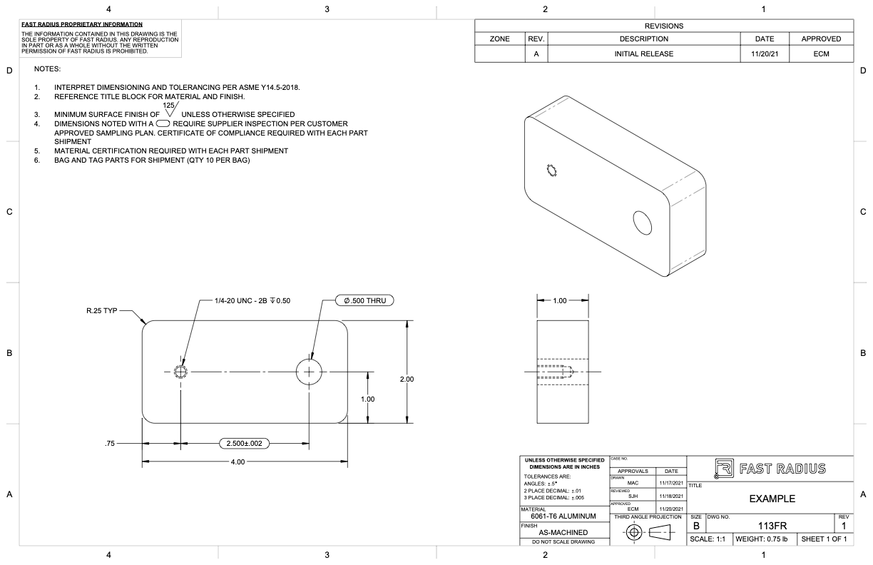
What to Include in Your Engineering Drawing Fast Radius

How to make a title box In engineering drawing, Title box in
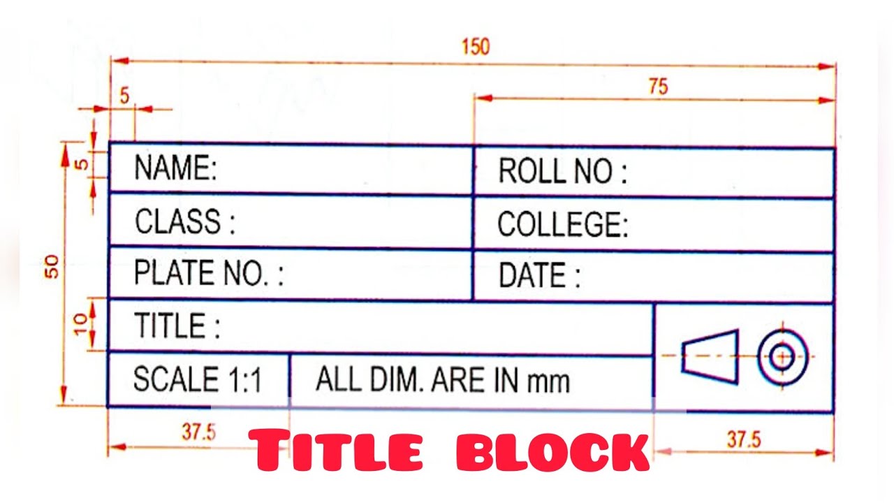
TITLE BLOCK in Technical drawing Engineering drawing Basic
Drawings Have An Information Box Or Title Block Containing Who Drew The Drawing, Who Approved It, Units Of Dimensions, Meaning Of Views, The Title Of The Drawing And The Drawing Number.
These Drawings Are Essentially The Blueprints Or Plans For Manufacturing A Wide Array Of Products And Structures.
Engineering Graphics Is Used In The Design Process For Visualization, Communication, And Documentation.
The Drawing Number, Which Is Generally A Unique Filing Identifier.
Related Post: