Engineer Drawing Symbols
Engineer Drawing Symbols - Web various symbols and abbreviations in engineering drawings give you information about the dimensions, design, and materials used. Here are more commonly used engineering drawing symbols and design elements as below. Most symbols have been in y14.5 since at least 1994. This manual sets forth the minimum requirements acceptable at gsfc for the preparation of engineering drawings for flight hardware and ground support systems. Click on the links below to learn more about each gd&t symbol or concept, and be sure to download the free wall chart for a quick reference when at your desk or. 10 a, but ‘a few amperes’). You may also be interested in our article that covers civil engineering abbreviations. Web every phase of engineering design starting from concept illustration all the way to the manufacturing phase. Why not just use a 3d model? These symbols are used to convey information about the design, construction, and materials used in the building. Note the comparison with the iso standards. Engineering drawing symbols play a vital role in communication among engineers and other stakeholders involved in the design and construction process. Eo 1.1 identify the symbols used on engineering p&ids for the following types of valves: These symbols and abbreviations are standardized by the american national standards institute (asmi) and the american society. An introduction to the different types of blueprint tolerances you will encounter with plenty of examples to make them easy to understand. Eo 1.1 identify the symbols used on engineering p&ids for the following types of valves: Web every civil engineering firm uses custom plan symbols in their drawings so it is important to check the drawing legend. Web engineering. Engineering drawings use standardised language and symbols. Web various symbols and abbreviations in engineering drawings give you information about the dimensions, design, and materials used. Work with runsom for your cnc programming projects. Web every civil engineering firm uses custom plan symbols in their drawings so it is important to check the drawing legend. Most symbols have been in y14.5. Specification (technical standard) structural drawing Web what are the most commonly used engineering drawing symbols and their meanings? 10 a, but ‘a few amperes’). Why not just use a 3d model? Here are more commonly used engineering drawing symbols and design elements as below. Web every phase of engineering design starting from concept illustration all the way to the manufacturing phase. To read and understand engineering fluid diagrams and prints, usually referred to as p&ids, an individual must be familiar with the basic symbols. It is more than simply a drawing, it is a graphical language that communicates ideas and information. Web various symbols and abbreviations in engineering drawings give you information about the dimensions, design, and materials used. Web engineering drawings (aka blueprints, prints, drawings, mechanical drawings) are a rich and specific outline that shows all the information and requirements needed to manufacture an item or product. An introduction to the different types of blueprint tolerances you will encounter with plenty of examples to make them easy to understand. Web blueprint symbols are graphical representations used on architectural and engineering drawings to indicate various features, elements, and components of a building or structure. They are 1) piping and instrument drawings (p&ids), 2) electrical single lines and schematics, 3) electronic diagrams and schematics, 4) logic diagrams and prints, and 5) fabrication, construction, and architectural drawings. Web engineering and drafting personnel in the preparation, revision, and completion of engineering drawings. Web learn the ins and outs of engineering drawing standards, such as iso and ansi, which govern the symbols, abbreviations, and notations used in drawings. Note the comparison with the iso standards.
Mechanical Engineering Drawing Symbols Pdf Free Download at

BASIC OF ENGINEERING DRAWING SYMBOL PART 1 YouTube

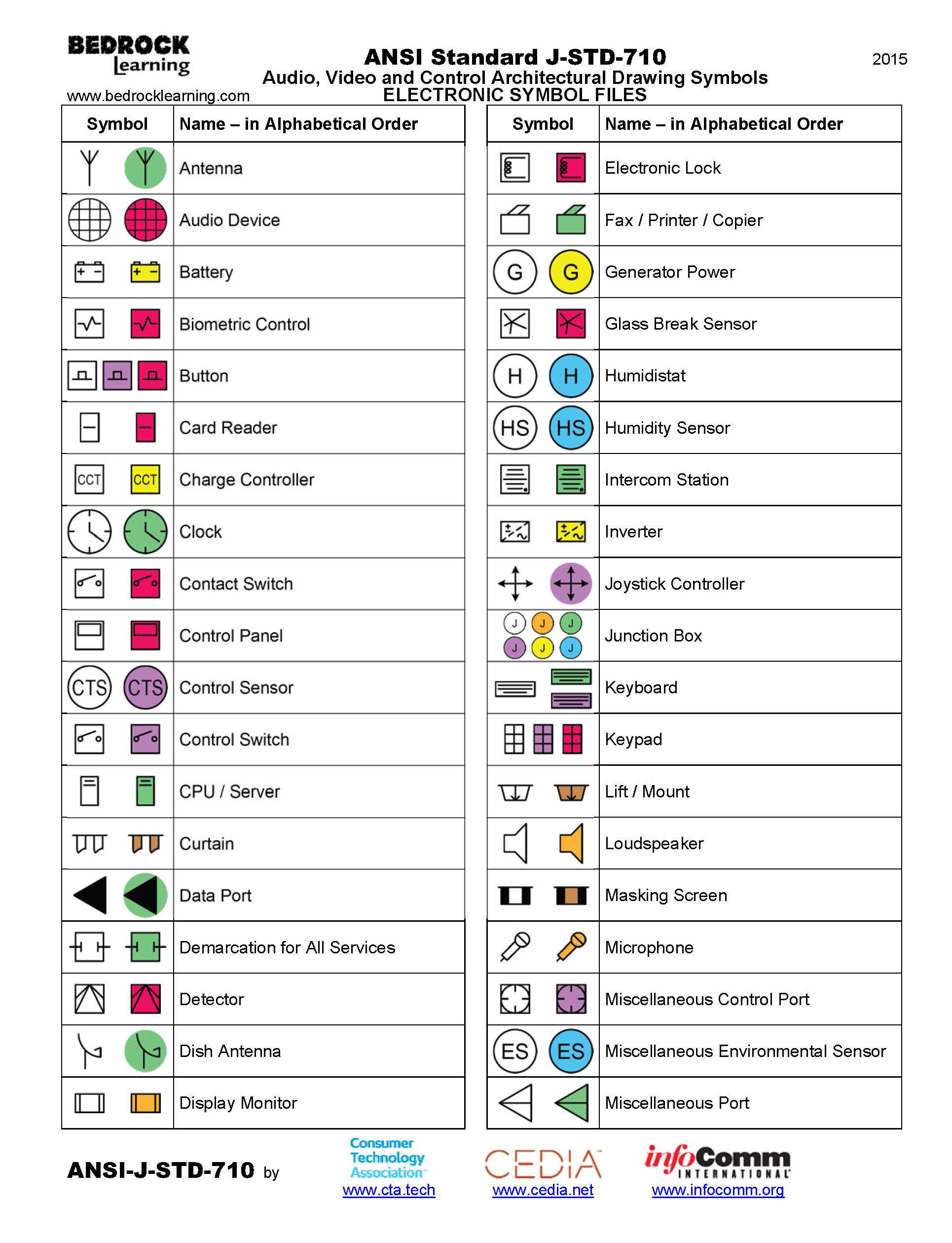
ANSI Standard JSTD710 Architectural Drawing Symbols Bedrock Learning
Unlike A Model, Engineering Drawings Note Much More Specific Information And Requirements, Such As:
Engineering Drawings Use Standardised Language And Symbols.
You May Also Be Interested In Our Article That Covers Civil Engineering Abbreviations.
The Purpose Is To Convey All The Information Necessary For Manufacturing A Product Or A Part.
Related Post: