Electrical Symbols For Drawings
Electrical Symbols For Drawings - Web you will learn how to define the symbols that should be used according to the type of electrical diagram, clarify the choice of a symbol that should be used on a plan, specify why representation standards are used, and associate a type of standard with a type of symbol through the use of this handbook. Capacitors (parallel lines) store energy in your system, while. There are some standard symbols to represent the components in a circuits. Each physical component (i.e resistor, capacitor, transistor) has a unique schematic symbol. Web basic electrical symbols contain earth electrode, cell, battery, resistor, etc. Web electrical symbols and electronic circuit symbols are used for drawing schematic diagram. Web common schematic drawing symbols microphone loudspeaker antenna, general symbol machine, general symbol * function m=motor g=generator generator, general symbol indicating instrument, general symbol * function v = voltmeter a = ammeter etc. Web this basic schematic symbols chart provides a comprehensive overview of the most commonly used symbols in electrical and electronic circuits. Web what is a circuit? In circuit diagrams, graphical symbols identify network components and devices. Let's go over som sample electrical symbols and what they represent. Web basic electrical symbols contain earth electrode, cell, battery, resistor, etc. Web electrical symbols are the most commonly used symbols in circuit diagramming. Every engineering office uses their own set of electrical symbols; Web electrical systems such as lights, switches, circuit breakers, distribution panels, and fixtures are denoted using. Every engineering office uses their own set of electrical symbols; Web some common symbols used in wiring diagrams include: These symbols represent components in schematic diagrams. There are some standard symbols to represent the components in a circuits. Each physical component (i.e resistor, capacitor, transistor) has a unique schematic symbol. Web electrical symbols are visual representations in electrical drawings and diagrams to convey information about components, devices, and connections within a circuit or system. Refer to the legend sheet in your set of plans for special symbols used in a particular set. Represented by various shapes depending on the type (e.g., npn or pnp) Web basic electrical symbols contain earth. Design & documentation > construction documentation. Web what is a circuit? Web some commonly used symbols in an electrical schematic symbols chart include: These symbols are used in engineering drawings, wiring schematics, circuit diagrams, and architectural blueprints. Refer to the legend sheet in your set of plans for special symbols used in a particular set. Web basic electrical symbols contain earth electrode, cell, battery, resistor, etc. Web common circuit diagram symbols (us ansi symbols) an electronic symbol is a pictogram used to represent various electrical and electronic devices or functions, such as wires, batteries, resistors, and transistors, in a schematic. Web create your circuit diagram. Electrical symbols or electronic circuits are virtually represented by circuit diagrams. Web electrical systems such as lights, switches, circuit breakers, distribution panels, and fixtures are denoted using various symbols described in legends. Web some common symbols used in wiring diagrams include: Frequently occurring technical phrases are commonly rendered as abbreviations (such as e.m.f., p.d.). The database is the official source of. The main goal of this tutorial is to show you the. It is also for electrical shock protection. It includes symbols for various components such as resistors, capacitors, diodes, transistors, switches, and more.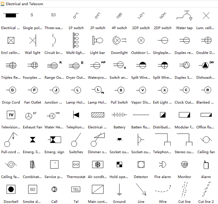
Electrical Drawing Symbols at Explore collection
Electrical Symbols Electrical Drawing Symbols Electrical Academia
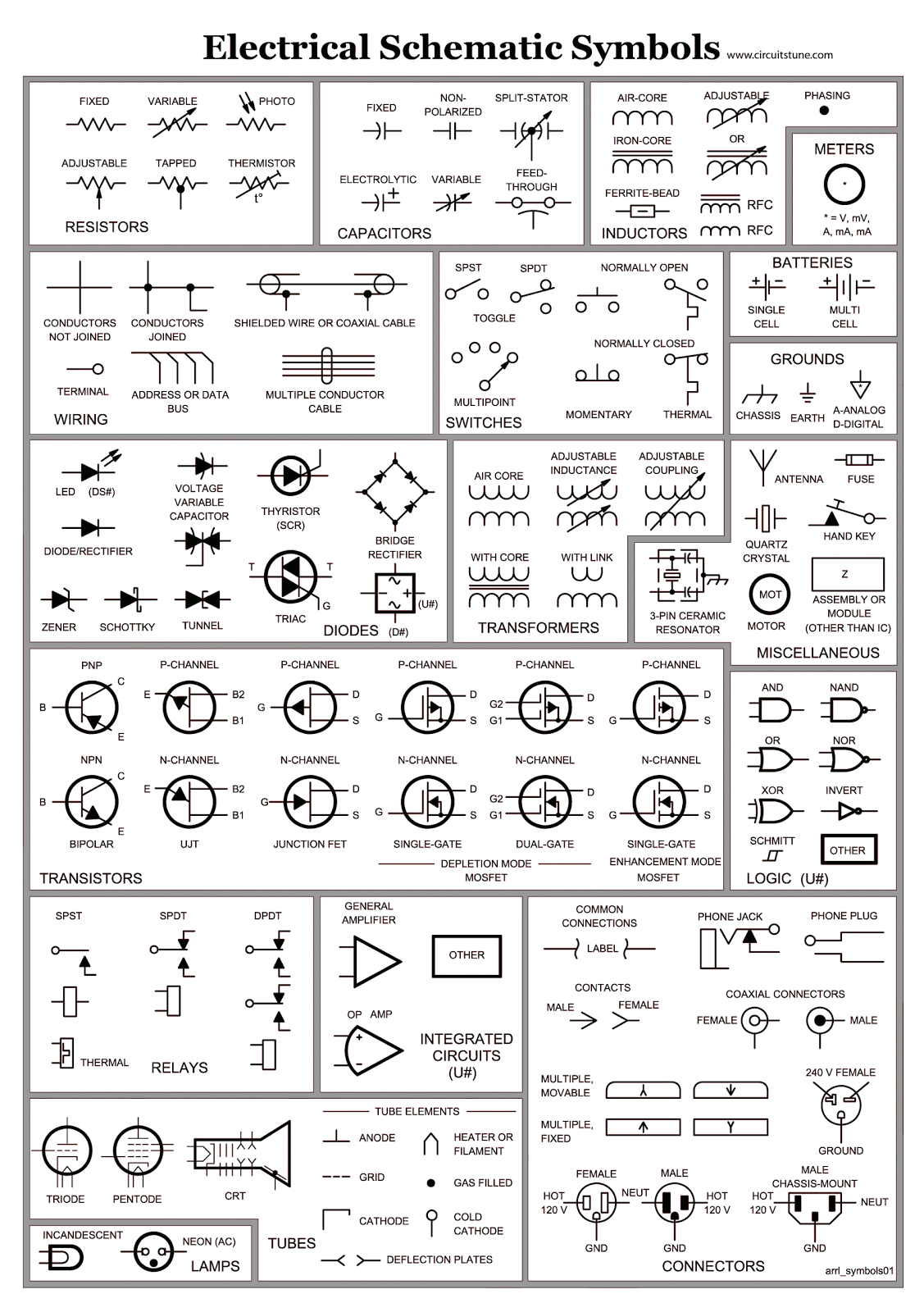
Electrical Schematic Symbols CircuitsTune
What Are Electrical And Electronics Symbols?
Legends Contain Abbreviations With Symbols Used For Appliances, Switches, Panels, And Other Fixtures Shown In A Plan.
Web Standard Electrical Plan Symbols Are Universally Accepted Representations Used To Denote Specific Elements Of An Electrical System In A Diagram Or Blueprint.
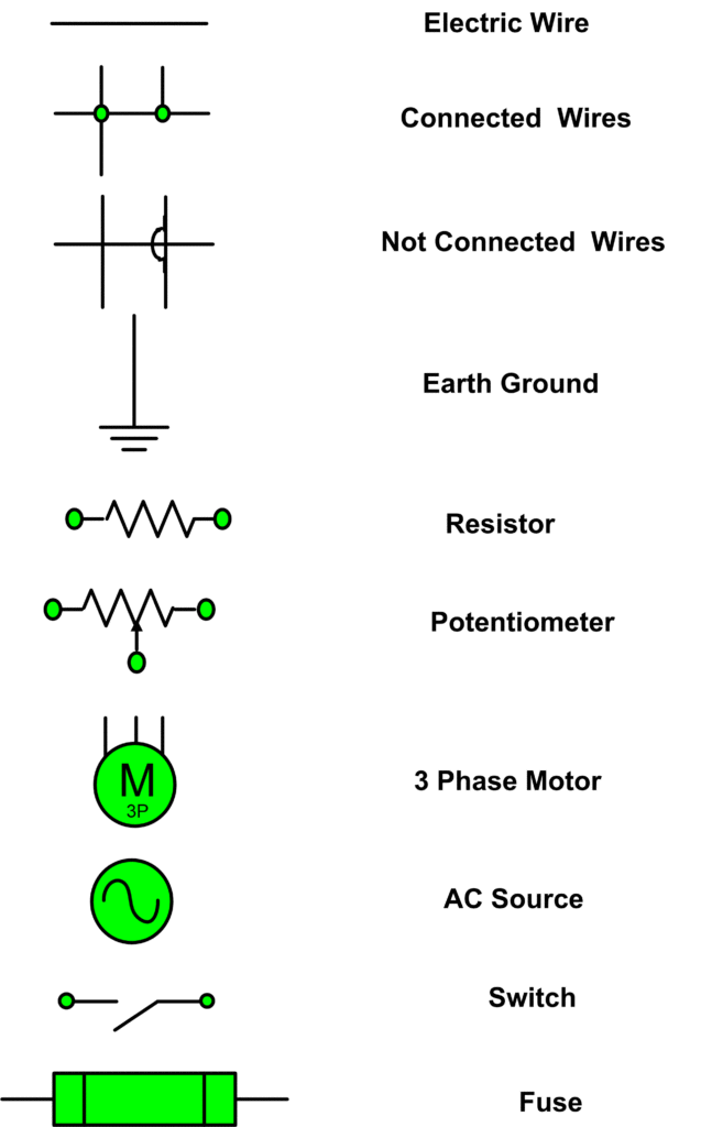
Each Physical Component (I.e Resistor, Capacitor, Transistor) Has A Unique Schematic Symbol.
Related Post: