Electrical Single Line Drawing Symbols
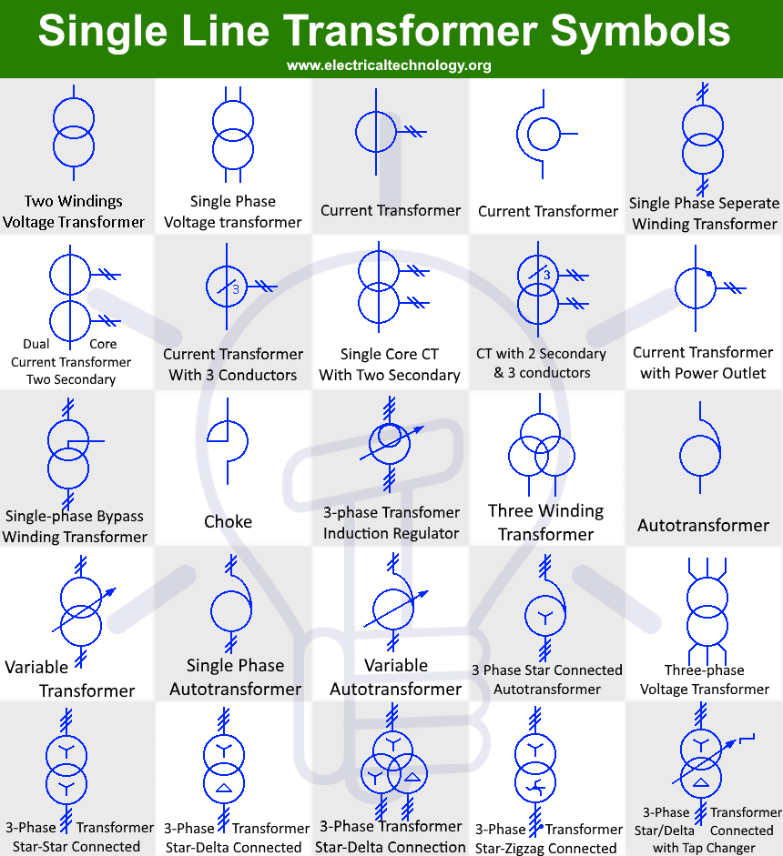
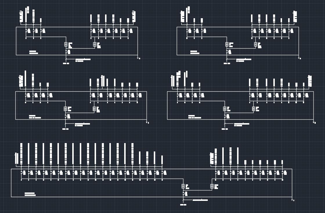
Electrical Single Line Drawing Symbols - Web some common symbols used in electrical single line diagrams include: By familiarizing themselves with these. Web single line diagram symbols are single line representations of device components or device subcomponents for use in constructing one line power diagrams, or single line. These symbols provide a standardized. The resistor symbol is a zigzag line, typically with two terminals. Electrical circuit diagram symbols are graphic representations of electrical components and their connections in a circuit. Web main components such as transformers, switches, and breakers are indicated by their standard graphic symbol. Web electrical symbols are used to represent the different components of the electrical system on a single line diagram. Single line diagram (sld) or, one line diagram. In this post you’ll learn what is single line diagram and why do we need it. Here are some of the key elements commonly found in slds: Web main components such as transformers, switches, and breakers are indicated by their standard graphic symbol. The overall diagram provides information on how the. A diagram which shows, by means of single lines and graphic symbols, the course of an electric circuit or system of circuits and the. The. It represents a passive component that limits the flow of electric current. By familiarizing themselves with these. Web these symbols may include lines, arrows, circles, squares, and letters, each representing a specific electrical component or function. These symbols provide a standardized. Electrical single line diagram guidance. Web electrical symbols are used to represent the different components of the electrical system on a single line diagram. A diagram which shows, by means of single lines and graphic symbols, the course of an electric circuit or system of circuits and the. Electrical single line diagram guidance. It represents a passive component that limits the flow of electric current.. By familiarizing themselves with these. These symbols provide a standardized. These symbols are standardized and used universally in the. In this post you’ll learn what is single line diagram and why do we need it. Web some common symbols used in electrical single line diagrams include: Web main components such as transformers, switches, and breakers are indicated by their standard graphic symbol. Electrical single line diagram guidance. The overall diagram provides information on how the. Web electrical symbols are used to represent the different components of the electrical system on a single line diagram. It represents a passive component that limits the flow of electric current. Web these symbols may include lines, arrows, circles, squares, and letters, each representing a specific electrical component or function. Web slds use standardized symbols to represent different electrical components. The life of a single line diagram. Electrical circuit diagram symbols are graphic representations of electrical components and their connections in a circuit. Web electrical one line diagram symbols can vary depending on the standards and conventions followed in different countries and industries. A single line diagram may start out in the design.Electrical Single Line Diagram Template (DWG) — LINE DRAW CAD LAB

ELECTRICAL LEGEND SINGLE LINE & SCHEMATIC SYMBOLS CAD Block And

Electrical One Line Diagram Symbols
The Resistor Symbol Is A Zigzag Line, Typically With Two Terminals.
Represented By A Circle With A Vertical Line And An Arrow Pointing Outwards.
Single Line Diagram (Sld) Or, One Line Diagram.
They Are Used To Represent And Communicate The.
Related Post:
