Electrical Schematic Drawing
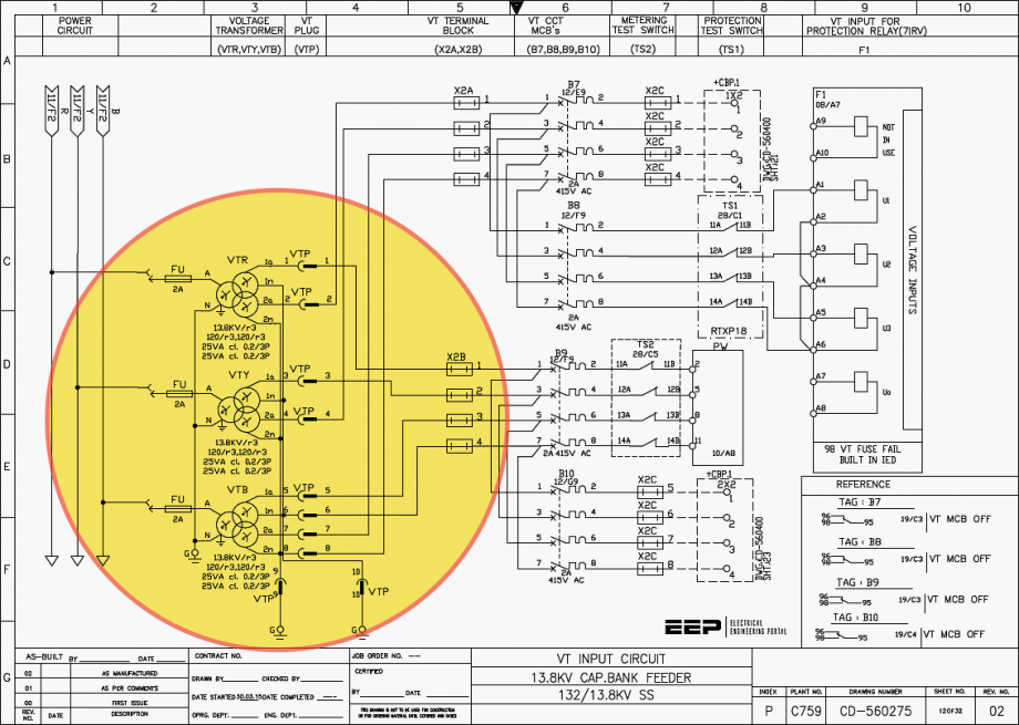
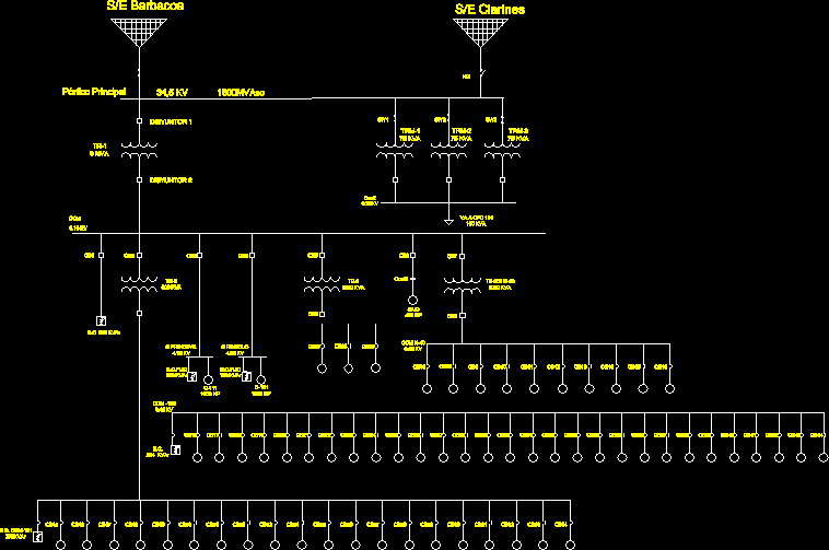
Electrical Schematic Drawing - Reading and understanding electrical schematics is an important skill for electrical workers looking to troubleshoot their. It shows the electrical components and interconnections of the circuit using standardized symbols and lines. The easy choice for creating schematic diagrams online. Web an electrical schematic, also known as a wiring diagram or circuit diagram, is a visual representation of an electrical circuit. It accelerates product development by simultaneously minimizing the repetitive tasks associated with developing electrical schematics. Its primary purpose is to show how the components of a circuit are laid out and interconnected, rather than to show a realistic, scaled representation of a finished engineering or architectural project. How to read electrical drawings. Understanding how to read and follow schematics is an important skill for any electronics engineer. Create diagrams visually by placing components with your cursor. Smartdraw's schematic diagram software is easy to use. Web welcome to digikey's free online schematic and diagramming tool. Ladder diagram or line diagram. Simplification of low and/or high voltage distribution, to provide an “overview” of the installation. Web electrical drawings are technical documents that depict and notate designs for electrical systems. Choose from electrical, power sources, transistors, relays, logic gates, and other standard symbols. Web welcome to digikey's free online schematic and diagramming tool. Lines connect fuses, switches, capacitors, inductors, and more. The symbols represent electrical and electronic components. Launch it instantly with one click. Understanding how to read and follow schematics is an important skill for any electronics engineer. Web an electrical schematic is a diagram that shows how all of the wires and components in an electronic circuit are connected. Create diagrams visually by placing components with your cursor. Its primary purpose is to show how the components of a circuit are laid out and interconnected, rather than to show a realistic, scaled representation of a finished engineering. The tool includes a comprehensive electronic symbol library and an integrated digikey component catalog that allows for a. Web electrical symbols and electronic circuit symbols are used for drawing schematic diagram. To enable the reader to separate and keep track of each step, each level of successive (sequential) operations from the first action (initiation) to the “ final act “. It shows the electrical components and interconnections of the circuit using standardized symbols and lines. How to read electrical drawings. Launch circuitlab or watch a quick demo video → 668k views 3 years ago electrical training topics. The symbols represent electrical and electronic components. Web an electrical schematic is a type of electrical design that provides a graphical depiction of an electrical circuit. Schematics are our map to designing, building, and troubleshooting circuits. Web a circuit diagram allows you to visualize how components of a circuit are laid out. Make schematic diagrams and drawings. Web among these you'll find commonly used electrical drawings and schematics, like circuit diagrams, wiring diagrams, electrical plans and block diagrams. Smartdraw's schematic diagram software is easy to use. Workers use these documents to install systems onsite. It accelerates product development by simultaneously minimizing the repetitive tasks associated with developing electrical schematics.
Electronic Schematics What You Need To Know

Electrical Schematic, Wiring Diagram 2D DWG Block for AutoCAD • DesignsCAD

How to Read and Interpret Electrical Shop Drawings Part One
Its Primary Purpose Is To Show How The Components Of A Circuit Are Laid Out And Interconnected, Rather Than To Show A Realistic, Scaled Representation Of A Finished Engineering Or Architectural Project.
The Easy Choice For Creating Schematic Diagrams Online.
On The File Tab, Select New, And Then Search For Engineering Templates.
Web Use The Electrical Engineering Drawing Type In Visio Professional Or Visio Plan 2 To Create Electrical And Electronic Schematic Diagrams.
Related Post: