Electrical Drawing Symbols
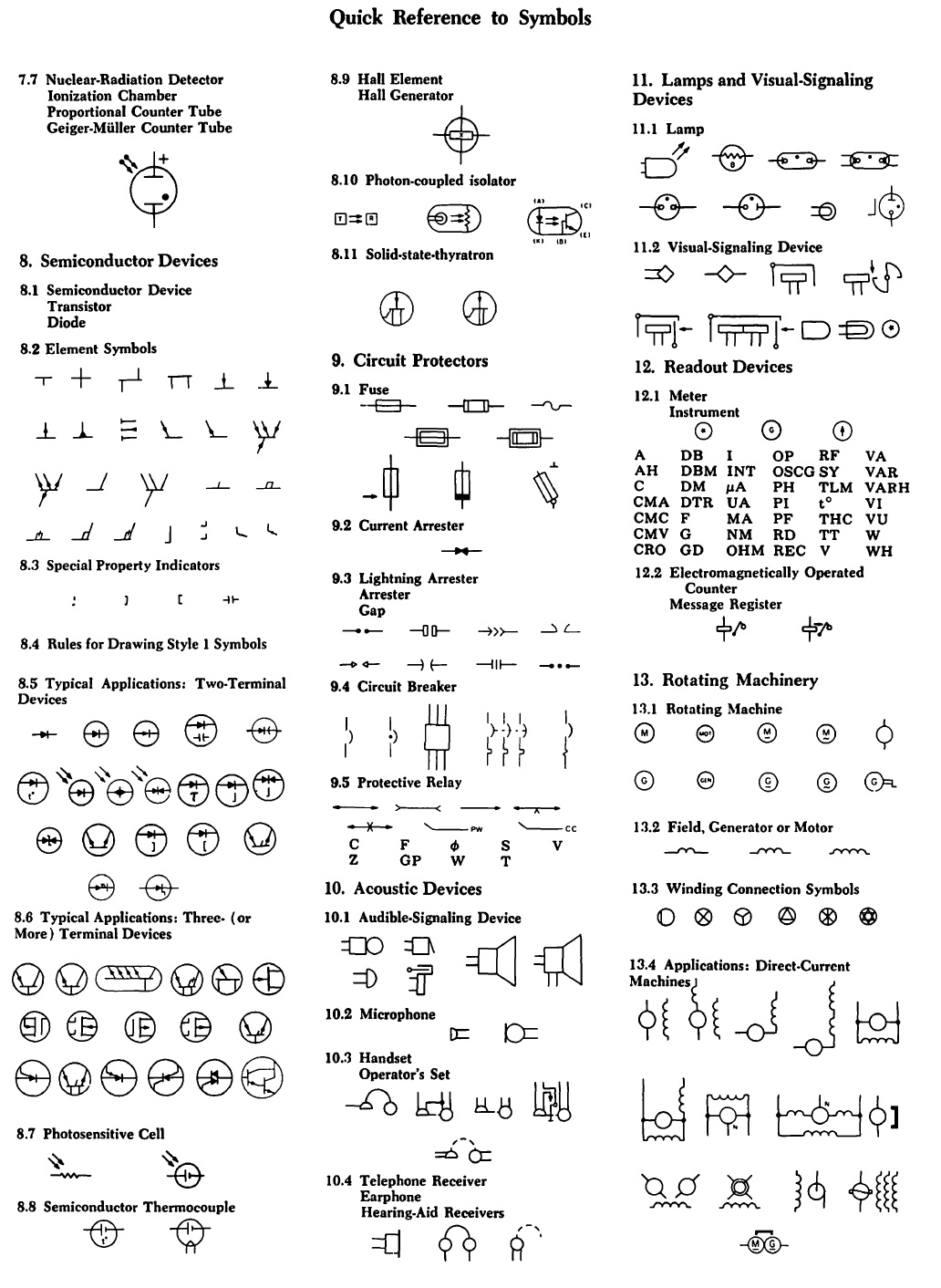
Electrical Drawing Symbols - Web an electronic symbol is a pictogram used to represent various electrical and electronic devices or functions, such as wires, batteries, resistors, and transistors, in a schematic diagram of an electrical or electronic circuit. Web we have provided a list of the most commonly used electrical symbols in electrical drawings. These symbols are standardized and universally recognized, making it easier for engineers, technicians, and electricians to understand and interpret electrical plans. Represented by a zigzag line. Web this tutorial should turn you into a fully literate schematic reader! Web a spst (single pole, single throw) switch is an on and off switch. Frequently occurring technical phrases are commonly rendered as abbreviations (such as e.m.f., p.d.). Web standard electrical plan symbols are universally accepted representations used to denote specific elements of an electrical system in a diagram or blueprint. However, the symbols below are fairly common across many offices. Represented by two parallel lines. Represented by two parallel lines. Frequently occurring technical phrases are commonly rendered as abbreviations (such as e.m.f., p.d.). The top symbol indicates that the switch is in the off position, which blocks the path of current. Web basic electrical symbols contain earth electrode, cell, battery, resistor, etc. Web electrical symbols or electronic circuits are virtually represented by circuit diagrams. Web an electrical symbol is a graphical representation used to represent electrical components or devices in schematic diagrams or circuit diagrams. Web electrical symbols and electronic circuit symbols are used for drawing schematic diagram. Refer to the legend sheet in your set of plans for special symbols used in a particular set. Web standard electrical plan symbols are universally accepted. The two schematic symbols below show the different states of an spst switch. Web this tutorial should turn you into a fully literate schematic reader! Import and export drawings to various file formats, such as visio. Web symbols (such as j, exp, cu) are used to indicate mathematical operations, chemical elements etc. We'll go over all of the fundamental schematic. Web circuit layouts and schematic diagrams are a simple and effective way of showing pictorially the electrical connections, components and operation of a particular electrical circuit or system. However, the symbols below are fairly common across many offices. Web standard electrical plan symbols are universally accepted representations used to denote specific elements of an electrical system in a diagram or blueprint. Web symbols (such as j, exp, cu) are used to indicate mathematical operations, chemical elements etc. Web it's quick, easy, and completely free. This article gives some of the frequently used symbols for drawing the circuits. Now, lets go through a industrial single line diagram. The bottom symbol indicates that the switch is on, which allows current to flow through the switch. You can depict a complex electrical circuit with the standard and simplified electrical symbols. Electrical circuit diagram symbols are graphic representations of electrical components and their connections in a circuit. Frequently occurring technical phrases are commonly rendered as abbreviations (such as e.m.f., p.d.). Web iec 60617 contains graphical symbols for use in electrotechnical diagrams. Web electrical symbols are visual representations in electrical drawings and diagrams to convey information about components, devices, and connections within a circuit or system. Web an electronic symbol is a pictogram used to represent various electrical and electronic devices or functions, such as wires, batteries, resistors, and transistors, in a schematic diagram of an electrical or electronic circuit. Web electrical symbols or electronic circuits are virtually represented by circuit diagrams. Web electrical symbols and electronic circuit symbols are used for drawing schematic diagram.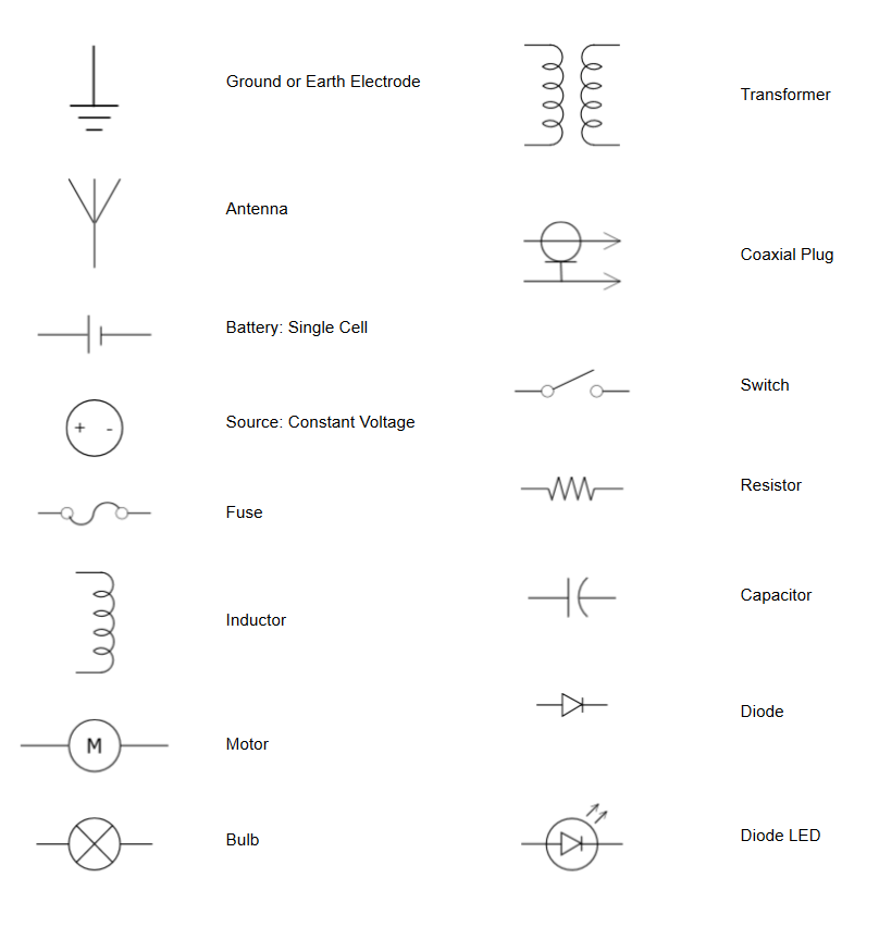
Electrical Symbols Try Our Electrical Symbol Software Free

Ansi Standard Electrical Schematic Symbols Wiring Draw
How to Read and Interpret Electrical Shop Drawings Part Two
Look For An App That Works On Mobile Devices, So You Can Draw Diagrams In The Workplace.
Single Pole, Single Throw (Spst) Switch.
These Symbols Are Standardized And Universally Recognized, Making It Easier For Engineers, Technicians, And Electricians To Understand And Interpret Electrical Plans.
Create More Than 280 Types Of Diagrams Effortlessly.
Related Post: