Drawing Machining Symbols
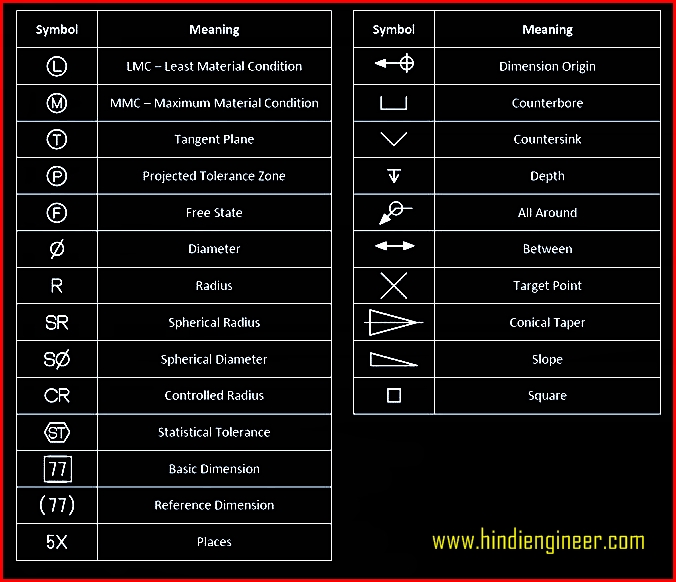
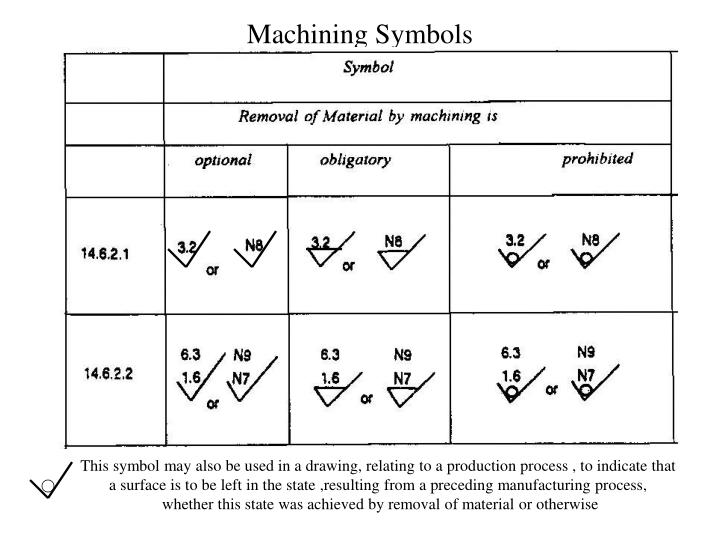
Drawing Machining Symbols - Here are more commonly used engineering drawing symbols and design elements as below. This basic symbol consists of two legs of unequal length. Symbols indicating target surface and the position of these symbols. Web basic types of symbols used in engineering drawings are countersink, counterbore, spotface, depth, radius, and diameter. Cut and paste to your drawing. While these cnc drawings and technical designs do the automatic part of machining, they also maintain the standard and quality during production. Gd&t flatness is a common symbol that references how flat a surface is regardless of any other datum’s or features. Web the technical drawing samples especially engineering drawings and machining blueprint symbols are the biggest resources in the manufacturing field. Parts of a machining blueprint machining blueprints include the blueprint title block, general tolerance block, projection types and types of feature tolerances. Engineering drawing is a fundamental skill in many branches of engineering, including mechanical, electrical, and civil engineering. The pictorial representation using these symbols is defined in iso 1302:2002. It involves the creation of accurate, detailed drawings that convey all the necessary information about a design, including dimensions, materials, and other specifications. If you are working on cnc machining parts or some other manufacturing process. Why abbreviations and symbols are needed for engineering drawing? Download and open the. You can use surface finish symbols to tell the manufacturer about your. You can also check out the gd&t symbols and terms on our site. Cut and paste to your drawing. Web the american society of mechanical engineers (asme) has published the y14.36m surface texture symbols standard, which illustrates the proper specification and use of surface texture symbols on technical. Web in the world of machining and manufacturing, the use of machining finish symbols is crucial for conveying important information about the surface finish of a part. While these cnc drawings and technical designs do the automatic part of machining, they also maintain the standard and quality during production. Asme also publishes the b41.6 surface texture standard, which contains definitions. Web standard symbols for mechanical components use such shapes as circles, ovals, arcs, triangles, squares, rectangles, polygons, lines, arrows, and other geometrical forms separately or arranged in complex patterns. Surface roughness symbols are used to communicate the required surface texture of machined and structural parts are used in industrial diagrams. Parts of a machining blueprint machining blueprints include the blueprint title block, general tolerance block, projection types and types of feature tolerances. The pictorial representation using these symbols is defined in iso 1302:2002. Web machine drawing is a pictorial representation of machine or machine components or the part of a product which provides outline/inline detail of a product including how it is going to manufacture with certain rules. Drawing or part number and revision. Cut and paste to your drawing. Web engineering drawing abbreviations and symbols are used to communicate and detail the characteristics of an engineering drawing. Web surface finish symbols are needed to represent the surface texture requirement to manufacturers. Web in learning to read machine drawings, you must first become familiar with the common terms, symbols, and conventions defined and discussed in the following paragraphs. The following paragraphs cover the common terms most used in all aspects of machine drawings. The title block of a blueprint can vary quite a bit across different companies. Why abbreviations and symbols are needed for engineering drawing? Asme also publishes the b41.6 surface texture standard, which contains definitions and measurement methods for. Common engineering drawing abbreviations used in cnc machining. Understanding these symbols is essential for achieving the desired surface quality and meeting specific design requirements.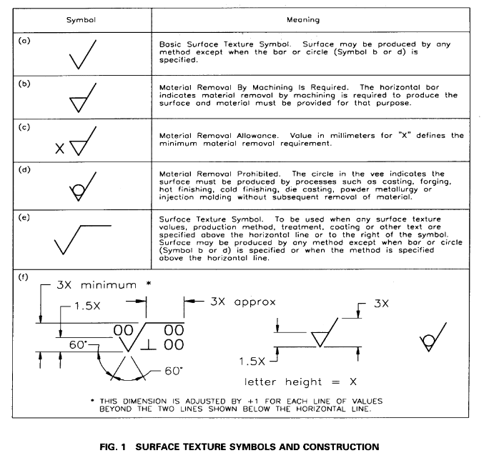
Surface Finish Lay Symbols
Machining Drawing Symbols Chart Machinist Blueprint Symbols Chart
Machining Symbols Chart
While These Cnc Drawings And Technical Designs Do The Automatic Part Of Machining, They Also Maintain The Standard And Quality During Production.
Web March 26, 2023 / 7 Minutes Of Reading.
Web The American Society Of Mechanical Engineers (Asme) Has Published The Y14.36M Surface Texture Symbols Standard, Which Illustrates The Proper Specification And Use Of Surface Texture Symbols On Technical Drawings.
The Pictorial Representation Using These Symbols Is Defined In Iso 1302:2002.
Related Post: