Drawing Electrical
Drawing Electrical - In this article, we will briefly describe several types of common electrical diagrams encountered in the field and explain their purpose. Draw circuits represented by lines. Web an electrical schematic is a diagram that shows how all of the wires and components in an electronic circuit are connected. Web an electrical diagram, also known as a wiring diagram or circuit diagram, is a visual representation of an electrical system or circuit. Web an electrical plan is a detailed drawing or diagram that shows the locations of all the circuits, lights, receptacles and other electrical components in a building. General notes, abbreviations, legends, and symbols, are found on the first page of the electrical drawings. Smartdraw's electrical symbols connect to circuit lines automatically. Updated on april 3, 2023. Smartdraw comes with thousands of detailed electrical symbols you can drag and. It shows the components of the circuit as well as the connections between them, using standardized symbols and lines to represent the electrical components and their functions. Draw circuits represented by lines. Create diagrams visually by placing components with your cursor. Web the electrical drawings consist of electrical outlets, fixtures, switches, lighting, fans, and appliances. Generate and update customized reports. Web free circuit diagram maker. When and how to use a wiring diagram. Professional schematic pdfs, wiring diagrams, and plots. The main thing here is that they rarely (never in my own experience) include the term ‘schematic’. Web an electrical floor plan (sometimes called an electrical layout drawing or wiring diagram) is a detailed and scaled diagram that illustrates the layout and placement of electrical. Lines connect fuses, switches, capacitors, inductors, and more. You will become familiar with the many types of diagrams and how to distinguish between them, as well as how to choose the appropriate diagram for a given situation and how to comprehend a logic sequence and a combinatory sequence. Start with a collection of electrical symbols appropriate for your diagram. Professional. Subscription includes autocad lt on desktop. Web an electrical plan is a detailed drawing or diagram that shows the locations of all the circuits, lights, receptacles and other electrical components in a building. It shows the components of the circuit as well as the connections between them, using standardized symbols and lines to represent the electrical components and their functions. Import existing files from visio®, gliffy, draw.io, and omnigraffle. Web an electrical schematic is a diagram that shows how all of the wires and components in an electronic circuit are connected. Web free circuit diagram maker. The main thing here is that they rarely (never in my own experience) include the term ‘schematic’. Use line hops if any lines need to cross. Ladder diagram or line diagram. Easily share dwg™ drawings with stakeholders. Updated on april 3, 2023. In this article, we will briefly describe several types of common electrical diagrams encountered in the field and explain their purpose. Start with a collection of electrical symbols appropriate for your diagram. The line will split into two and connect each end to the symbol in exactly the right place. Subscription includes autocad on desktop, web, mobile, and seven specialized toolsets. Web an electrical floor plan (sometimes called an electrical layout drawing or wiring diagram) is a detailed and scaled diagram that illustrates the layout and placement of electrical components, fixtures, outlets, switches, and wiring within a building or space.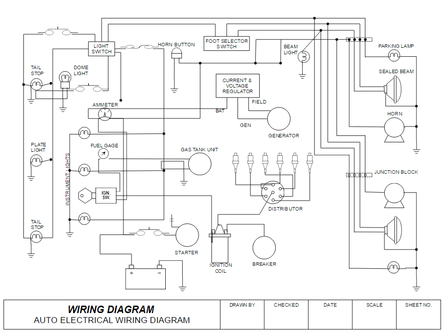
How to Draw Electrical Diagrams and Wiring Diagrams
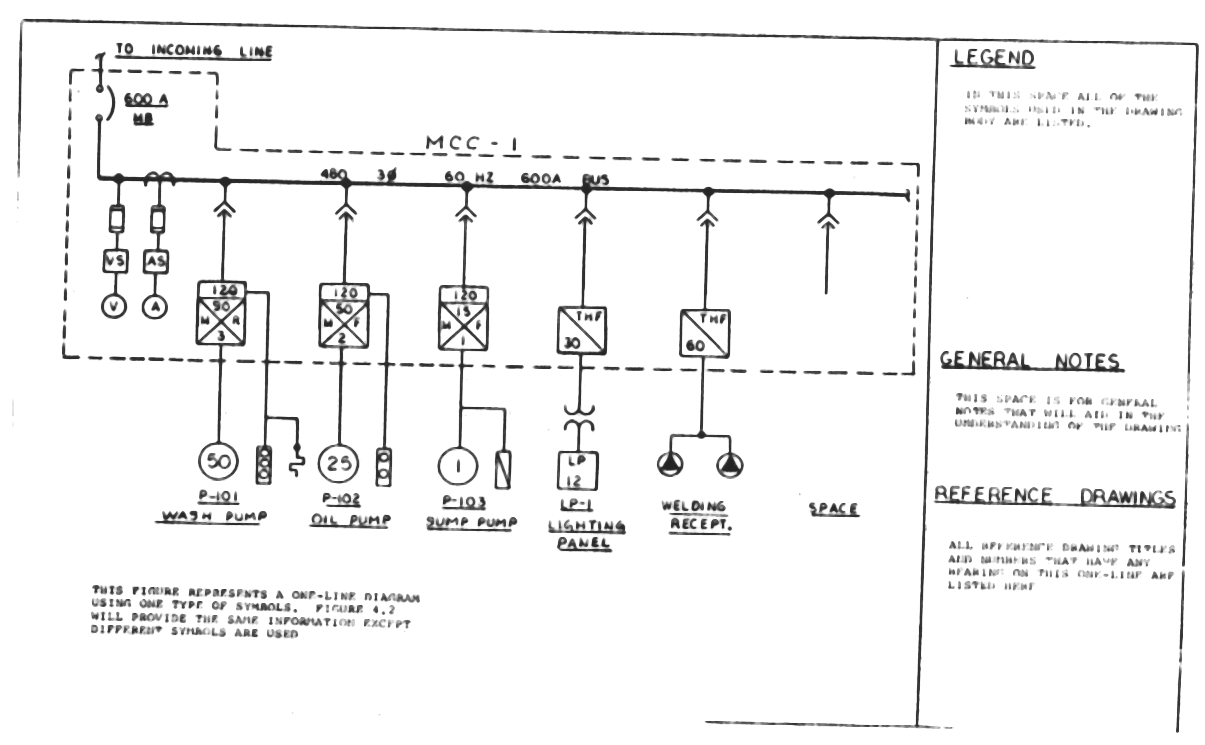
Electrical Engineering Tutorial Types of Electrical Drawings
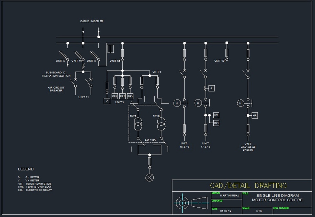
Sample of Electrical Drawings Martin Irsaj
When And How To Use A Wiring Diagram.
Select One Of The Following:
It Shows How The Electrical Wires Are Interconnected And Can Also Show Where Fixtures And Components May Be Connected To The System.
To Add A Symbol To Your Electrical Design, All You Have To Do Is Drag A Symbol To A Line And Drop It.
Related Post: