Draw The Logic Circuit
Draw The Logic Circuit - Use the wire tool to connect your elements. Web draw a logic circuit of given boolean function using aoi.(aoi stand for and, or, not gate) 1. Web using only and, or, and not gates, draw circuits that compute the value of each of the propositions a → b, a ↔ b, and a ⊕ b. Web chapter 7 boolean algebra. For each of the following propositions, find a. Logic circuits are designed to perform a particular function, understanding the nature of that function requires a logic circuit truth. In this post you will practise drawing logic gates diagrams using the following logic gates: Detailed steps, logic circuits, kmap, truth table, & quizes. These gates are used in combinational and sequential circuit design. Let’s begin with a semiconductor gate circuit in need of simplification. First you will need to. Logic circuits are designed to perform a particular function, understanding the nature of that function requires a logic circuit truth. From simple gates to complex sequential circuits, plot timing diagrams, automatic circuit generation, explore standard ics, and. Ii) state the value of p if a, b. Know it all about logic diagram. Logic circuits are designed to perform a particular function, understanding the nature of that function requires a logic circuit truth. Web solve practice questions using an online terminal. Purpose and benefit of logic diagram. Boolean algebra expression simplifier & solver. Ii) state the value of p if a, b. Logic circuits are designed to perform a particular function. Computers often chain logic gates together, by taking the output from one gate and using it as the input to another gate. Web circuit diagram is a free application for making electronic circuit diagrams and exporting them as images. P= (a and b) or (not c) i) draw a logic gate. Web you have a multitude of different logic gates that operate within a computer. Better understand your logic gates. Web boolean algebra expression simplifier & solver. While visualizing the single gates and the wires are relatively simple, arranging the elements on. Web drawing diagrams such as logic circuits in a readable way is a complicated task. Let’s begin with a semiconductor gate circuit in need of simplification. Logic circuits are designed to perform a particular function, understanding the nature of that function requires a logic circuit truth. Web logic gates are used to carry out logical operations on single or multiple binary inputs and give one binary output. Web freehand drawing to sketch out initial outlines of logic gates during brainstorming sessions. Understanding the nature of that function. The logic gate software has all the logic symbols you need to design any kind of. F= a′b′c + a′bc + ab′. Click run to start the simulation. Design circuits online in your browser or using the desktop application. Looking for a logic circuit tool? These gates are used in combinational and sequential circuit design.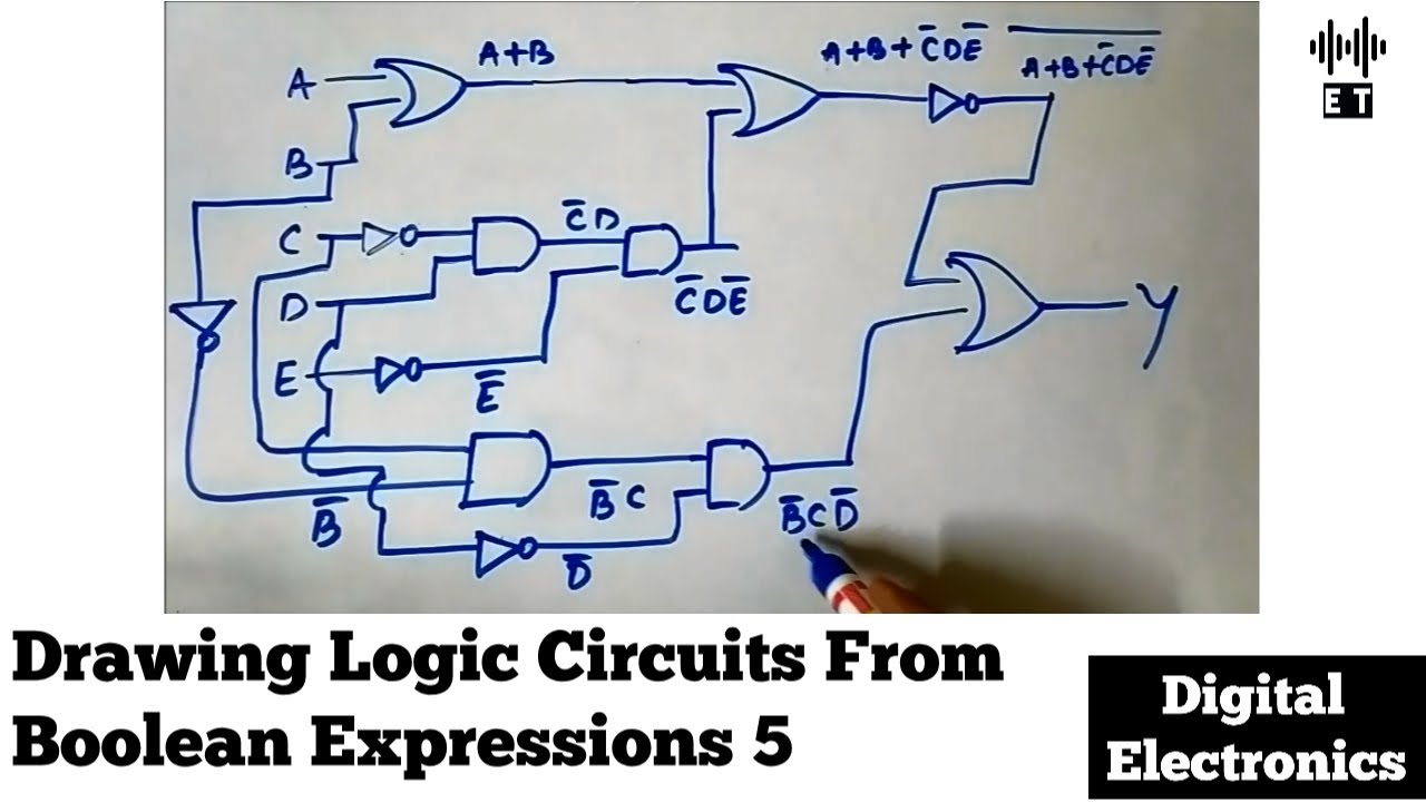
Drawing Logic Circuits From Boolean Expressions Important Questions 5

DRAWING LOGIC CIRCUIT USING EXPRESSION LSTOU EDUCATION YouTube

Draw Logic Circuit Online Wiring Draw
Web Using Only And, Or, And Not Gates, Draw Circuits That Compute The Value Of Each Of The Propositions A → B, A ↔ B, And A ⊕ B.
Boolean Algebra Expression Simplifier & Solver.
Web Logic Gates Are The Heart Of Digital Electronics.
Place It On The Board.
Related Post: