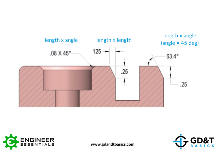
Chamfer Callout On Drawing
Chamfer Callout On Drawing - In addition to the usual dimension display properties, chamfer dimensions have their own options for leader display, text display, and x display. Today, many cad software can automatically add dimensions to a drawing. Rfs is the default condition of all geometric tolerances by rule #2 of gd&t and requires no callout. Web dimensioning chamfers is done with a call out that specifies the length of the chamfer along with the angle of the chamfer. How to make a break edge. This provides safety for both the part and the person using the part. The terms “break edge” and “deburr” are similar. Is it in the standard? I have a cylindrical part with a chamfer at each end. If the selection was part of a hole feature, the precision, tolerance, fit class tolerance, and shaft class tolerance values from that feature are. Create the dimensions needed (angle and/or distance) create leader note, inserting created dimensions as needed to create desired call out. See figure 2 for chamfer dimensioning examples. Is it in the standard? Creating a hole or thread callout: When i create a shown dimension for a chamfer in a drawing the leader seem to be fixed to an angle or. Web break edge callouts are specified directly on the drawing to reference a certain surface or as a note e.g. Web when using a leader to call out a chamfer (ie. Web you can create the dimension wanted in a couple of steps. I am attaching an image of the part in question and the only way i can really. You must select the chamfered edge first. However, one of those edges is on a diagonal face, so the 0.25mm chamfer is being shown as 0.33 (see below). Web basic dimensioning is the addition of only functional size values to drawing entities. Web dimensioning chamfers is done with a call out that specifies the length of the chamfer along with. Click chamfer dimension on the dimensions/relations toolbar or click tools > dimensions > chamfer. Web the typical callout will most often be used as part of a repeating pattern such as a bolt hole circle, to identify the hole sizes or angle between the holes. Web when using a leader to call out a chamfer (ie. The terms “break edge” and “deburr” are similar. Another common application is to identify a common chamfer size on a component. What is the correct way to call out a 45 degree chamfer? .040 x 30) to my knowledge the.040 be the depth into the material and the 30 degrees is the angle from the centerline. Xgrigorix (specifier/regulator) (op) 26 sep 05 14:51. Kenat (mechanical) 10 aug 07 12:57. Assuming you work to asme standards (when asking this type of question i suggest you specify what standards you work to.) Jj11142 (mechanical) (op) 16 nov 12 16:15. This is good only for sketches and preliminary design drawings. Web dimensioning chamfers is done with a call out that specifies the length of the chamfer along with the angle of the chamfer. Web 7 feb 24 12:17. Rfs is the default condition of all geometric tolerances by rule #2 of gd&t and requires no callout. Web to insert chamfer dimensions into a drawing:
Introduction to AutoCAD Chamfer YouTube

Chamfer Dimensioning GD&T Basics

SolidWorks Tutorial How to Add Chamfer Dimension In Solidworks Drawing
Web 10 Aug 07 12:39.
Web Break Edge Callouts Are Specified Directly On The Drawing To Reference A Certain Surface Or As A Note E.g.
This Provides Safety For Both The Part And The Person Using The Part.
If The Selection Was Part Of A Hole Feature, The Precision, Tolerance, Fit Class Tolerance, And Shaft Class Tolerance Values From That Feature Are.
Related Post: