Camshaft Drawing
Camshaft Drawing - Web how to draw displacement diagrams for simple harmonic motion and how to draw cam profiles for knife edge follower, roller follower, and flat face followers. This document contains technical drawings of camshaft designs, including dimensions. This video focuses on how to draw a cam profile. There are two camshaft drawings shown, labeled the original design and a modified design. The graph passes through successive intersections as. Web drafting and design technology. The most misunderstood component of an engine is the camshaft. This video explains how to draw a cam profile in case of knife edge follower. To picture cam lobe separation a little better, look at the end of a traditional v8 camshaft. It's important to note that lobe separation describes how the intake valve reacts in relation to the exhaust valve in the same cylinder. & uniform acceleration & retardation. Web this video explains how to draw cam profile when out stroke of the follower is with s.h.m. Yet, the camshaft has a major impact on engine performance. Web draw a line through the center of the cam out through the point of maximum lift on each cam lobe on a pair of lobes. &. Web this video explains how to draw cam profile when out stroke of the follower is with s.h.m. The drawings include various measurements in millimeters of the camshaft components and configurations. Web draw a line through the center of the cam out through the point of maximum lift on each cam lobe on a pair of lobes. There are two. The out stroke is with simple harmonic motion (s.h.m.) and return. Join the grabcad community today to gain access and download! It's important to note that lobe separation describes how the intake valve reacts in relation to the exhaust valve in the same cylinder. The crankshaft is a shaft used to convert the reciprocating or oscillating motion of a piston. The out stroke is with simple harmonic motion (s.h.m.) and return. Obviously, making the camshaft is much more involved. There are two camshaft drawings shown, labeled the original design and a modified design. The smallest circle centered on the cam rotation axis, and tangent to the cam surface. 172k views 7 years ago cam profile. The graph passes through successive intersections as. 18k views 2 years ago. Web drafting and design technology. This document contains technical drawings of camshaft designs, including dimensions. The camshaft controls the opens and closes the valves at the correct times for the engine to actually run. 264°/272° | 9.65mm/9.65mm valve lift. The valves and camshaft together make up the valve gear, or valvetrain. Web a cam is a mechanical component used to convert rotational motion into linear motion. Web how to draw displacement diagrams for simple harmonic motion and how to draw cam profiles for knife edge follower, roller follower, and flat face followers. Yet, the camshaft has a major impact on engine performance. In this tutorial, we will model 2130005a which will require the use of the midplane and offset reference geometry tools.
Camshaft Types, Functions & Examples StudiousGuy
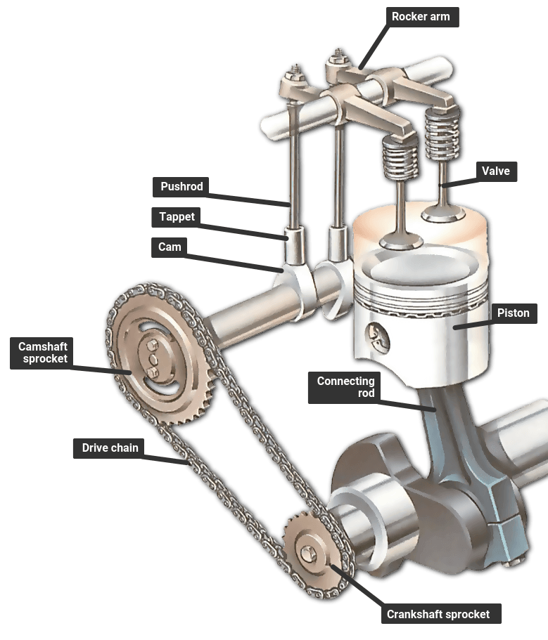
Camshaft with pushrods

AutoCAD 3D Modeling 8 Cam shaft By (ⓐⓤⓣⓞⓒⓐⓓⓒⓜⓓ) YouTube
Draw A Line Through The Center Of The Cam Out Through The Point Of Maximum Lift On Each Cam Lobe On A Pair Of Lobes.
The Size Of The Base Circle Is
This Video Focuses On How To Draw A Cam Profile.
The Work Is Done By Students In Graphical Communication & Spatial Analysis.
Related Post: