Architectural Drawing Dimensions
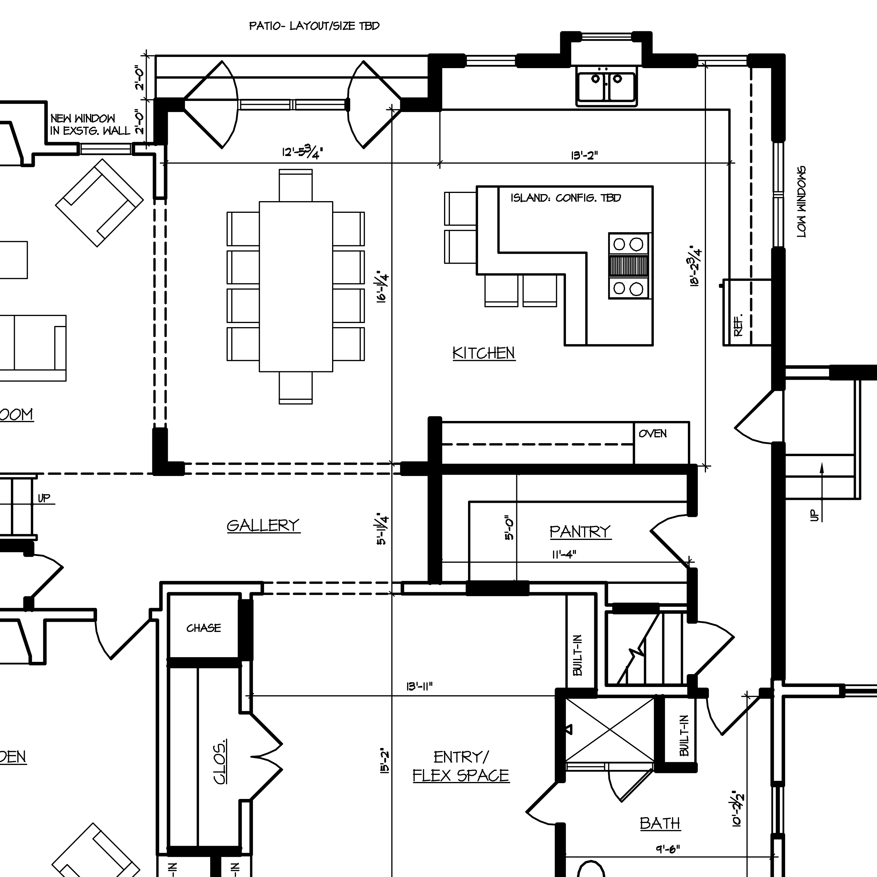
Architectural Drawing Dimensions - What this means is the face of a concrete column can be an inch in either direction from where you think it should be. 12, 18, 24, 30, 33, 36, or 48 inches. Although there are tens of hundreds of guidelines for dimensioning drawings properly, in this article, i have selected only some of the most popular ones that frequently appear in a drawing. Width (in) length (in) horizontal zone: Web architectural blueprints are technical drawings that represent the design and details of a building project. Dimensioning columns even to half an inch is probably asking for unachievable precision. In architectural and structural sketches and drawings, the numerals are usually above an unbroken dimension line. The builder’s guide to architectural drawings. Web for most of the architectural drawing best practices, the source is national cad standards (ncs, usa). Web an architectural drawing is a sketch, plan, diagram, or schematic that communicates detailed information about a building. 36 x 48” (914 x 1219mm) Web in machine sketches and drawings, in which fractions and decimals are used for dimensions, the dimension line is usually broken near the middle to provide open space for the dimension numerals. A comprehensive reference database of dimensioned drawings documenting the standard measurements and sizes of the everyday objects and spaces that make up. Gypsum board partitions in plan: Web here are the standard us architectural drawing sizes: Although there are tens of hundreds of guidelines for dimensioning drawings properly, in this article, i have selected only some of the most popular ones that frequently appear in a drawing. Web the standard base kitchen cabinet sizes are listed below. 36 x 48” (914 x. Web ansi standard us engineering drawing sizes: Width (in) length (in) horizontal zone: 12, 18, 24, 30, 33, 36, or 48 inches. 36 x 48” (914 x 1219mm) An architectural drawing is the technical rendering of a house or other structure that is both an illustration of what the final home will look like and also a tool used by. 5.8 x 8.3” (148 x 210mm) arch paper sizes. Gypsum board partitions in plan: Architecture drawings are important for several reasons: An architectural drawing is the technical rendering of a house or other structure that is both an illustration of what the final home will look like and also a tool used by engineers, contractors, designers, and builders to execute the construction. Web the purpose of a floor plan is show a dimensioned and scaled map of a building’s interior spaces, depicting the relationship to one another, connections between the interior and exterior, and the location of key elements such as. Architectural scale, a fundamental concept in the design and perception of buildings and spaces, serves as an essential bridge between abstract ideas and tangible realities. Standard views used in architectural drawing. Web for most of the architectural drawing best practices, the source is national cad standards (ncs, usa). Scaled 2d drawings and 3d. Web a comprehensive reference database of dimensioned drawings documenting the standard measurements and sizes of the everyday objects and spaces that make up our world. Architects and designers create these types of technical drawings during the planning stages of a construction project. Web ansi standard us engineering drawing sizes: The builder’s guide to architectural drawings. Web architectural blueprints are technical drawings that represent the design and details of a building project. Web all architecture drawings are drawn to a scale and as described here in great detail, there are set scales that should be used depending on which drawing is being produced, some of which are below: Web here are the standard us architectural drawing sizes:
Easy Architectural Drawing at GetDrawings Free download

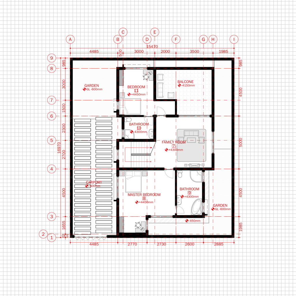
Residential Modern House Architecture Plan with floor plan metric units

Architectural Graphic Standards Life of an Architect How to plan
9 X 12” (229 X 305Mm) Arch B:
Web An Architectural Drawing Is A Sketch, Plan, Diagram, Or Schematic That Communicates Detailed Information About A Building.
16.5 X 23.4” (420 X 594Mm) A3:
Identify The Key Features Of The Object That Need To Be Dimensioned, Such As Walls, Windows, Doors, Or Other Elements.
Related Post: