778 Draw The Shear And Moment Diagrams For The Beam
778 Draw The Shear And Moment Diagrams For The Beam - 7.3k views 2 years ago statics. The shear force is the resultant of the stresses caused by shear deformation: Web for example, if w(x) is uniform, v(x) will be linear. In each problem, let x be the distance measured from left end of the beam. You'll get a detailed solution from a subject matter expert that helps you learn core concepts. Web our calculator generates the reactions, shear force diagrams (sfd), bending moment diagrams (bmd), deflection, and stress of a cantilever beam or simply supported beam. This problem has been solved! Equation 6.1 suggests the following expression: (b) determine the magnitude and location of the maximum absolute value of the bending moment. The reaction force on the load is calculated as: In each problem, let x be the distance measured from left end of the beam. To find these weak points, we need to check the internal loading at every point along the beam’s full length. Establish the m and x axes and plot the values of the moment at the ends of the beam. 90k views 3 years ago statics.. Shear and bending moment equations. In each problem, let x be the distance measured from left end of the beam. We go through breaking a beam into segments, and then we. Web 7.78 draw the shear and moment diagram for the beam. This problem has been solved! This involves calculating the shear and moment forces at the support points and at any points where the section changes. Establish the m and x axes and plot the values of the moment at the ends of the beam. This problem has been solved! N = σ ⋅ a = f a ⋅ a = f unsurprisingly, the normal force. You'll get a detailed solution from a subject matter expert that helps you learn core concepts. Statistics and probability questions and answers. Draw the shear and moment diagrams for the beam. Web when designing a beam it is important to locate the points of maximum shear and maximum moment and their magnitudes because that’s where the beam is most likely to fail. You'll get a detailed solution from a subject matter expert that helps you learn core concepts. (b) determine the magnitude and location of the maximum absolute value of the bending moment. Equation 6.1 suggests the following expression: Web our calculator generates the reactions, shear force diagrams (sfd), bending moment diagrams (bmd), deflection, and stress of a cantilever beam or simply supported beam. 7.3k views 2 years ago statics. Web the equation also suggests that the slope of the moment diagram at a particular point is equal to the shear force at that same point. N = σ ⋅ a = f a ⋅ a = f unsurprisingly, the normal force is equal to f, because the beam must be in equilibrium with the external forces. We are asked to draw the shear and moment diagrams. This is an example problem that will show you how to graphically draw a shear and moment diagram for a beam. Start at one end, (point a), of the beam and work toward the other end. Once these are determined, derive the shear and moment functions. Skyciv beam tool guides users along a professional beam calculation workflow, culminating in the ability to view and determine if they comply with your region's design.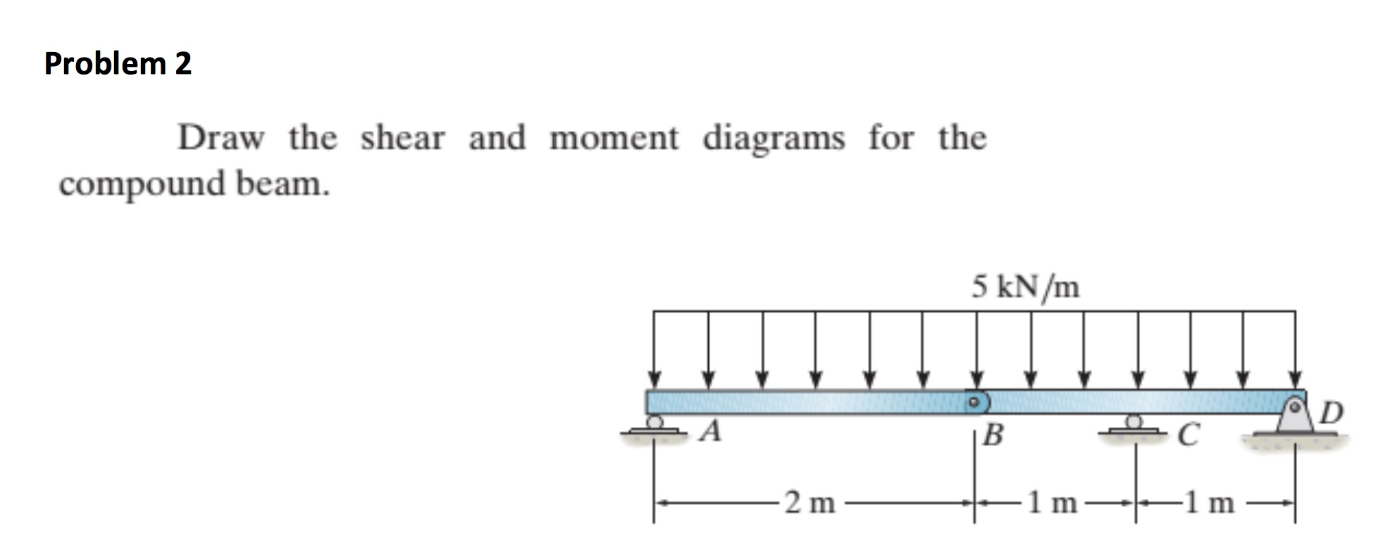
draw the shear and moment diagrams for the beam chegg

Draw The Shear Diagram For The Beam
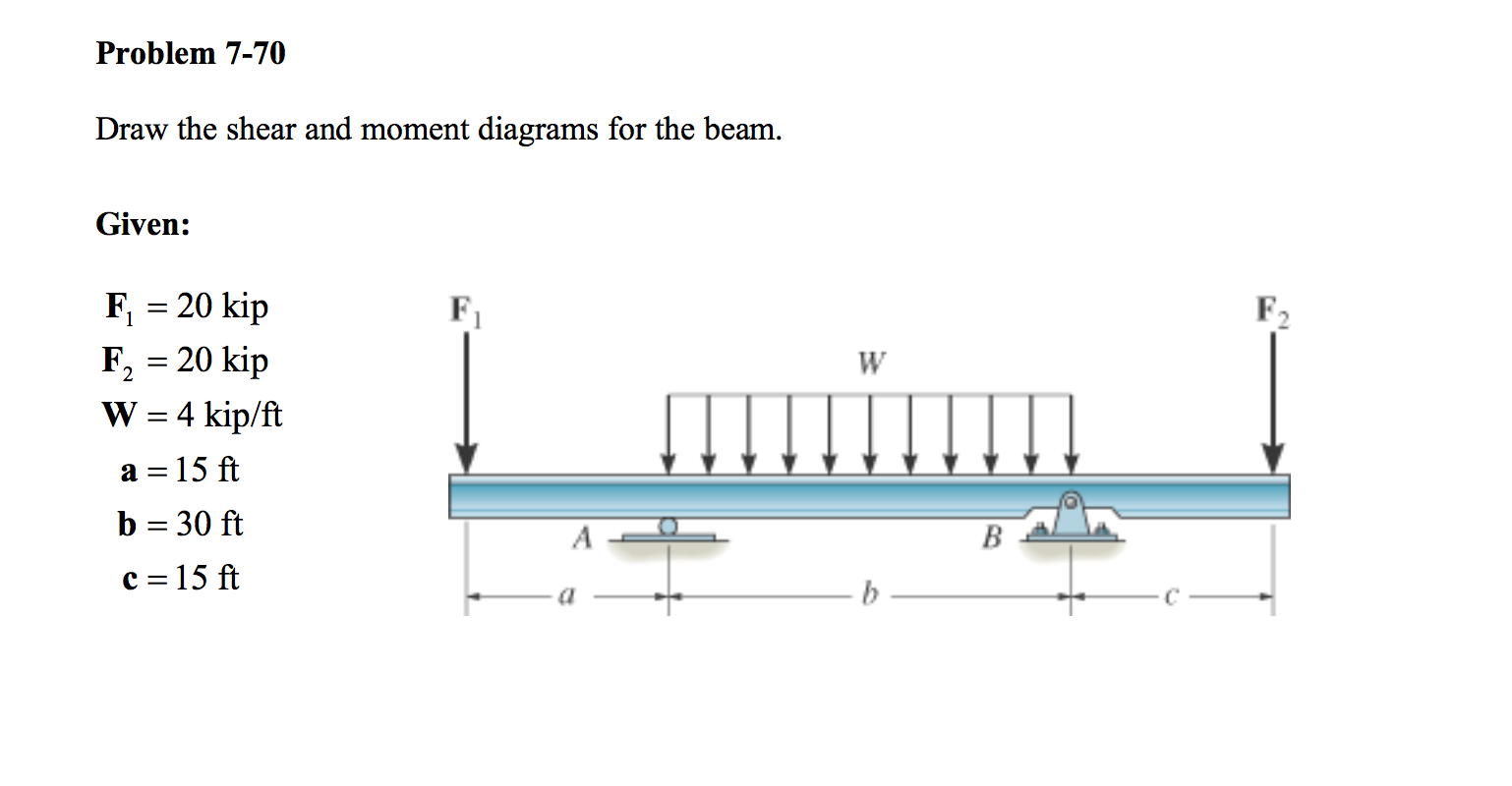
Solved Draw the shear and moment diagrams for the beam.
Web 7.78 Draw The Shear And Moment Diagram For The Beam.
291K Views 2 Years Ago Engineering Statics.
To Find These Weak Points, We Need To Check The Internal Loading At Every Point Along The Beam’s Full Length.
Figures 1 Through 32 Provide A Series Of Shear And Moment Diagrams With Accompanying Formulas For Design Of Beams Under Various Static Loading Conditions.
Related Post: