3 View Drawing
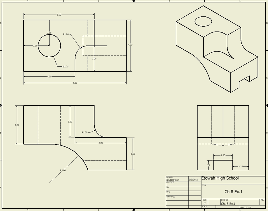
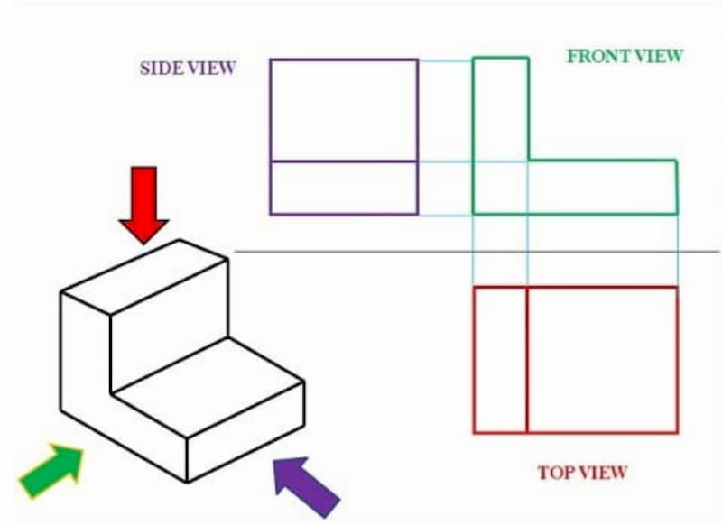
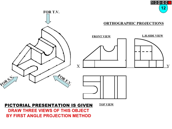
3 View Drawing - There are three types of pictorial views: This beginner level tutorial explains. The view orientations used are based on the orientations (front, right, and top) in the part or assembly. From buildings to landscapes and even still life subject matter, understanding how to draw in three point perspective will make drawing much easier! There are three types of pictorial views: A perspective view presents a building or an object just as it would look to you. The depth dimension is common to the top and side views. Web the two main types of views (or “projections”) used in drawings are: The width dimension is common to the front and top views. Web the standard 3 view option under insert > drawing view creates three related default orthographic (front, right, left, top, bottom, and back) views of a part or assembly displayed at the same time. The view orientations used are based on the orientations ( front, right, and top) in the part or assembly. Web from a 3d pictorial of an object, draw a multiview drawing using the three standard views. The depth dimension is common to the top and side views. If you understand multiview drawings, hidden lines, and can draw the three standard. The distortions that the third vanishing point brings into your composition often has a very artistic effect and makes even the most simple concept more interesting. By gd&t basics on march 30, 2021. Web the two main types of views (or “projections”) used in drawings are: 22k views 7 years ago introduction to drafting. The width dimension is common to. This is a simple tutorial on how to draw a 3 view orthographic projection drawing in autocad from a given isometric drawing. Draw the front, top, and right side orthographic views from the provided isometric view. The height dimension is common to the front and side views. Web the standard 3 view option under insert > drawing view creates three. Web the standard 3 view option under insert > drawing view creates three related default orthographic (front, right, left, top, bottom, and back) views of a part or assembly displayed at the same time. I have added many listings from air. Many thanks to david livesay for the hard work done in creating this list of free flight model plans and articles that appeared in american aircraft modeler, and for giving permission to duplicate it. Web three point perspective is great when you wish to render objects or scenes from an abnormally high or low point of view. This video explains three view blueprints/drawings and how to determine front views, top views, and right side views. Thus, a 2d view has to convey everything necessary for part production. There are three types of pictorial views: The depth dimension is common to the top and side views. 742 views 7 months ago engineering graphics. The distortions that the third vanishing point brings into your composition often has a very artistic effect and makes even the most simple concept more interesting. The view orientations used are based on the orientations (front, right, and top) in the part or assembly. An orthographic view or orthographic projection is a way of representing a 3d object in 2 dimensions. From buildings to landscapes and even still life subject matter, understanding how to draw in three point perspective will make drawing much easier! How the views are laid out on a drawing depends on whether 3 rd angle or 1 st angle projection is being used. Orthographic views can show us an object viewed from each direction. Web three view drawings judging criteria (what do we really look at) the drawings:
3 Views Of Isometric Drawing at Explore collection

Engineering Drawing Views & Basics Explained Fractory (2022)

Three View Orthographic Drawing at Explore
Download And Consult The 3 View Drawings For A Wide Range Of Dassault Aviation Civil And Military Aircraft.
22K Views 7 Years Ago Introduction To Drafting.
Web Three Point Perspective Drawing Is An Essential Skill To Aspiring Artists.
This Is A Simple Tutorial On How To Draw A 3 View Orthographic Projection Drawing In Autocad From A Given Isometric Drawing.
Related Post: